Most of us know that to get the best possible WiFi signal, you want there to be as few walls as possible between you and the Access Point. But that might soon change, as researchers at MIT have found a way to make surfaces increase signal strength. Called RFocus, the technique uses a wall panel covered in simple antennas to dynamically focus or reflect RF energy towards a intended receiver.
The normal methods to increase wireless range usually involve increasing the transmitter output or adding larger, more efficient, or directional antennas to the receivers and transmitters. But these techniques are limited when you need to the reduce power consumption and size of the devices. The MIT teams approached the problem from a completely different angle, by optimizing the environment.
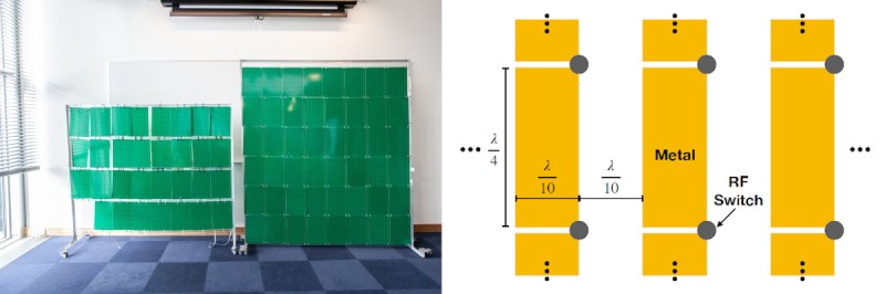
The wall panel in question consist of 94 PCBs, each containing 40 passive antenna elements in the form of copper rectangles. Each element is a quarter wavelength long (125 mm for 2.4 Ghz), and on its own it doesn’t have any real effect on the signals, allowing it to pass through the panel. Between the ends of elements are small RF switches, that can close to combine two antenna elements into single half wavelength antenna, creating a reflector. When this is applied across the panel in different patterns it can effectively beamform the signal to focus it at different points in space.
The RF switches are connected to shift registers, which are all controlled via a single SPI bus with an Arduino. Each RF switch is activated in a pseudo-random sequence, changing the configuration of the panel 10,000 times in 100 ms. The signal strength at the receiver is reported to the panel controller for each configuration, allowing the controller to select the best configuration for any single transmitter. In a scenario where multiple low-power sensor nodes are deployed, this can allow the receiver to “focus” on each node in turn. The full paper is a very interesting read, downloadable as a PDF.
RF is generally considered the black magic of electronics, but it can all become a bit clearer with a basic knowledge of antenna theory and modulation schemes.
Thanks to [Qes] for the tip!


Here is a serious question. What would be ideal for cheap RF blocking and perhaps allowing one range of frequency to pass through? Aka just IR warmth and Visible light. Is there any plastics or wall paper that can be used?
A metal mesh, similar to what you find on the front of a microwave oven. If you want to let a specific RF frequency through, stick a wire through a mesh such that you basically have a 1/4 wave antenna on the outside connected to another 1/4 wave antenna on the inside.
If I put a 1/2 wave antenna halfway through my microwave door, can I cook a hot fog on the outside end?
Just asking, for a friend.
hot fog = hot dog
but hey, it could end up that way anyway!
Yes. I used this method to have cellular coverage in a faraday cage in between measurements. A coax with a 1.8Ghz sleeve dipole on each end. I pushed it through the ventilation shaft.
Signal was not very strong but we have a base station nearby. It was enough to make and receive calls.
How did you “turn it off” when taking measurements?
I do this with a BNC panel-mount barrel connector (i.e., a feedthrough). Just stick your antenna of choice on each side of the BNC. Remove antenna(s) when not needed. The BNC can remain in the penetration panel. The naked BNC doesn’t pass much at all. You can cap it if you’re worried, but a (good) room I tested came in at better than 110 dB attenuation which didn’t change if that BNC was capped (at least in the 64-130 MHz range of interest for that room — YMMV at much higher frequencies).
I’ve wondered for quite a while if an array of passive patch antennas could be used a bit like this. Apartment dwellers know what a total PITA the crowded wifi space can be and “just make a Faraday cage” is a totally unreasonable solution.
Maybe there could be some sort of a hybrid where a panel or set of panels can be tuned to minimize outside signals then set up in a non-volatile and passive way to maintain that tuning.
I remember trying to measure and map the RF signals from my neighbors to try and strategically place grounded foil in an attempt to block some of the interference. But it didn’t work all that great.
So, it’s a software-configurable zone plate, acting as a dynamically-adjustable passive repeater. Not as efficient as a real passive repeater because it has to throw a fair bit of the energy away (it being a zone plate, and not adjusting wavefront phase), and also sensitive to polarization. Still, very neat.
I was a radio field tech in the last century: When the topography (and link margin) was favourable we would install big reflectors on mountaintops to act as passive repeaters, in lieu of setting up a full-blown active repeater. It was a one-time manual configuration, adjusting the angle of the panel(s) to optimize the link between two fixed ground stations. It would have been nice to just let a computer optimize it like this, but then we would have had to supply power to the site, and would have needed a panel 5-10 times larger to counter the inefficiency of this approach.
I think the idea is that because it is dynamically “tuned” at 100kHz cycles, it can track moving focal points or “hop” amongst mulitple focal points to maximize signal to those targets. That is something a fixed panel can’t do and better than nothing.
This is mind blowingly cool
One of my pet projects is a passive repeater. It is funny how they have fallen so out of favor these days. I described what I want to do to a few people and they just give me a blank stare and start talking about arduinos and esp modules. They seem to miss the elegant simplicity and the fact that you don’t need any power for a passive solution.
Exactly. One of the best lessons I got as a wet-behind-the ears field tech was from a more senior guy: A customer complained his pager (yeah, this was the ’80s) didn’t work in his ground-floor office. The engineers in head office couldn’t figure it out, and were proposing a local repeater to boost signal. The experienced tech took one look at the office location, then grabbed two antennas and a coil of coax: put one on the 5th floor roof and one on the ground floor, connected by the coax. Happy customer. Embarassed engineers. And pissed off sales guy: he missed out on his commission for a repeater sale.
Not a product for tin foil hat enthusiasts.
Line the hat with PCBs that contain half wavelength dipoles and the brain scans will pass right through…
I ground my tin foil cap by running a copper wire from it to heels of my shoes. Except for the shoes, the wire and tin foil are concealed under clothing.
BTW, I’m thinking gold foil would work much better than aluminum foil, does anybody know a cheap source for that?
Am I right in thinking of this as being a bit like a reconfigurable fresnel lens, but for RF instead of light. That you are using the RF switches to connect/disconnect sections of the wall to optimise or maximise constructive interference for one target location.
And if that is the case, could you could also optimise it to maximise the destructive interference from once source location to attenuate the signal strength on the other side.
It’s a phased array. But in this case they don’t know the phase initially (to get the best signal at the receiver), so they use random phase adjustments and watch the receiver strength, and stop adjusting when they get the best signal strength.
That’s the thing: it’s specifically NOT a phased array. They can’t and don’t adjust the phase. All they can do is turn on or off discrete resonant elements: the scatter from the active elements is phase-coherent only because the incident radiation is; they can’t control each element’s relative phase. They best they can hope for is that it all comes out in the optimization wash, so to speak.
That said, yes, sure, it’s trivial to change the optimization criterion to minimize rather than maximize signal strength at the target point. I suppose that might interest the tinfoil hatters, but then a sheet of foil is simpler.
Yep, phased array. Not in a classical sense, but you end up with the same effect.
Nope, not at all a phased array. In a phased array you get to control the phase of the individual elements. That’s the whole point. This device absolutely does not do that. Instead it just turns on or off individual scattering elements. This is much more like a zone plate, not a phased array.
Because it can’t adjust the phase that each element emits, it has intrinsically lower efficiency than a phased array. Basically it only turns on elements that contribute positively to the desired result: it cannot flip the phase of an element on demand; it can only turn it off if it doesn’t help.
Actually, it’s even worse than a zone plate: A zone plate is usually polarization-agnostic. This device is polarized, so won’t work at all if you’re unlucky with incident polarization, and on average will scatter “correctly” only half the incident radiation.
Absolutely. By controlling the emission phase, beam forming is possible.
Much like “the thing” designed by Theremin and found behind a carved wooden US seal in a US embassy, you could modulate the rf panels in response to audio in the room, and amplitude modulate the reflection of a 2.4GHz beam used to illuminate the panel.
https://en.m.wikipedia.org/wiki/The_Thing_(listening_device)
A related expired patent:
https://patents.google.com/patent/US5496966?oq=Neil+Hightower
So much copper, so little benefit, the idea is a great exercise in EE maths for students but a dud from a product point of view. Surely there is a smarter way to do this without using so much material?
How much copper do you think is present there? And how much is too much? A rough estimate makes it about 300 grams in that whole array. About as much as in two meters of 2mm^2 (14awg) branch circuit wiring, and less than the amount in your microwave oven.
I read through the quick blurb and the thing that I am unclear about is how they turn the various elements on and off. They are happy to state that each antenna costs just cents and they have thousands of them, so we are already talking some bucks, but I suspect the steering on the antennas, either mechanical or electronic would add significantly to the cost, and also depending on how the system that configures them works, how physically fragile is it? And what do you do if you have multiple devices that need a signal? Interesting research but it leaves a lot of questions unanswered at least in the quick write up.
The linked pdf is a little lightweight, but does have answers to much of that.
e.g. the RF switch is referenced: minicircuits JSW2-33DR-75
Thank you for the reference. From mouser, these are a buck a pop in 3000 piece reels, so this is not an inexpensive solution if you need one for each element, and that still leaves the question as to what has 3000 i/o pins to turn the switches on and off. At least it does not sound physically fragile, but it does not sound inexpensive to me.
The idea is that it’s steerable. Which is useful in some applications. But if you just want to get higher power over to some fixed spot, there are passive ways to do it. Lenses, reflectors, selective surfaces.
Now I want to build a 100×100 cell box kite quad antennas out of mylar space blankets with mechanical shuttering to give me over the horizon UHF TV capability.
Fly an antenna, mix the whole UHF band up to some microwave frequency, aim the microwave antenna down, receive downstairs and convert back to UHF band.