If you’re going to ditch work, you might as well go big. A 1,024-pixel thermochromic analog clock is probably on the high side of what most people would try, but apparently [Daniel Valuch] really didn’t want to go to work that day.
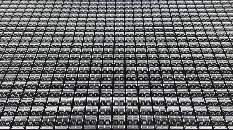
The idea here is simple: heat up a resistor by putting some current through it, lay a bit of thermochromic film over it, and you’ve got one pixel. The next part was not so simple: expanding that single pixel to a 32 by 32 matrix.


To make each pixel square-ish, [Daniel] chose to pair up the 220-ohm SMD resistors for a whopping 2,048 components. Adding to the complexity was the choice to drive them with a 1,024-bit shift register made from discrete 74LVC1G175 flip flops. With the Arduino Nano and all the other support components, that’s over 3,000 devices with the potential to draw 50 amps, were someone to be foolish or unlucky enough to turn on every pixel at once. Luckily, [Daniel] chose to emulate an analog clock here; that led to additional problems, like dealing with cool-down lag in the thermochromic film when animating the hands, which had to be dealt with in software.
We’ve seen other thermochromic displays before, including recently with this temperature and humidity display. This one may not be the highest resolution display out there, but it’s big and bold and slightly dangerous, and that makes it a win in our book.


1) get a giant petry dish
2) put that 1024 heat element array under it
3) put it inside an enviroment at 10C
4) turn on the pixels at 30C
Congratulations, you can now print bacteria on a petry dish
You could implement Conway’s Game of Life using … life.
Interesting project at an interesting scale! Nicely done!
If you use diodes instead of resistors, you could use a multiplex driver.
Well, if you use a matrix and multiplexing, you can make it simple. But why would you do it simple? Then you don’t need 1024 flip flops. There are many ways to do it, I like simple, but highly repetitive patterns. It is very pleasing to watch :)
Very interesting project and nice build.
The PCB thickness look like regular 1.6mm, I would have thought that using extra thin (say 0.6mm) would reduce the cooling down time quite a bit. Also using smaller packaged (0805) instead of the super expensive 2512 would also reduce thermal inertial as you only need to elevate the temperature above a threshold.
By the way, is there any room temperature measurement for software current control/compensation?
What is the average power consumption to display time?
Also, because it look like the primary intend is only to display time, why having a orthogonal matrix? And not quadrant + dial arrangement with just 2 different length of hands, again, it would drastically reduce the BOM.
The 0805s are cheaper, but assuming you want the same size clock and pixels, you would need more of them, and then the difference is price is not that much. The pixels wouldn’t look so nice either, because you’d get dark lines between the resistors.
The pcb is actually quite thick, 3.2mm. First for structural reasons, but when designing I was afraid of too high heat leakage, which would smear the pixels and the pixel power might not be sufficient. It turns out 250mW is more than enough if you allow second for transients. We’ll see in winter.
The total power consumption is about 8A at 4.6V. The flip flops can go down below 3V with supply voltage, nice way to regulate winter/summer
Nice project! This would be fun to do a version with IR LED’s so a smartphone camera could view it but invisible to the naked eye. Allows interaction for anyone with a phone rather than dedicated fluke.
Nice idea and good progress write up too!
Does anyone have a sense for how much heat the resistors actually put out?
quote from linked project page “The pixels are made out of 2512 size resistors, each dissipating 250mW (5V/50mA)” all that is dissipated as heat, unless you up the power a lot then it’s like 99.5% heat, 0.5% orange light.
If you up the power even more, you can even have sound, but only once. I tried to repair a switch mode PSU and while thinking about the picture on the scope, ther suddenly was a loud bang, allmost like a small caliber gunshot. It took me a few seconds to realise, that the 0,22R 2512 current shunt just ceased to exist, no traces left, I could not even see remains of dust. Apperantly the transformer had internal shorts (nearly no inductance), the transistor overheated and turned on permanently and dumped the charge from the mains electrolytic into this resistor.
I misread the title and thought it was a thermal imaging clock so it could only be read by thermal imaging camera. It’s actually a bit more useful
Wow, I AWLAYS wanted to make exactly this! So cool to see that you did!!!
I wanna know how much power it takes when it’s being used for its intended use case. Counting by hand from the attached photos, It looks like ~100 of the pixels (~10% of the entire display) are lit up, and the author says that the whooole thing can consume 250W, so I’m assuming that “clock mode” consumes 200 – 250W, but I guess that that would be contingent on whether the pixels need to be run at 100% heat to get the image to come out.
I’d be interested to know the actual numbers.
You could use heatlamps mounted on the ceiling of a large building full of people and project a matrix of heated areas so the people gravitate to the heated parts if they want to stay warm or avoid them if keeping cool was appropriate. A ceiling view of the people and where they are willing to stand could also work as a clock face. :-) You could have the same effect with obnoxious sounds coming from a matrix of speakers or a matrix fo free but low power wi-fi access points.
Chicago – Does Anybody Really Know What Time It Is? (Does anybody really care?)
https://www.youtube.com/watch?v=9FzCWLOHUes
This is one of the coolest projects that has ever been featured on Hackaday. I bet you could increase resolution, while reducing bleeding and input lag by cutting the thermochromic film into a 32×32 grid of small, separated squares.
The technology is incredible, you could easily scale it down to have nanometer pixel displays. You could also use this to make volumetric displays by adding resistors to a solid block of transparent thermochromic material.
If you don’t have thermochromic material, you can use lard – in room temperature it’s opaque and white, when heated it’s transparent and brown :D
I have added few videos on YT
https://www.youtube.com/playlist?list=PLIZ-1iHyG9xULpwT6HNwn9H9CDPh0pSpV
Very very cool. I researched the thermochromic materials a bit, sadly they are made with very toxic chemicals and have a rather limited life span, being very sensitive to UV light. Themal cycling also degrades the material quickly, which sadly is what we need to do. In 6 months, the display will fade dramatically.
Cool tech for the blind!