3D Audio Imaging With A Phased Array Microphone

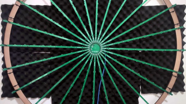
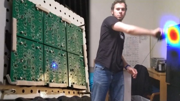
Remember the scene from Blade Runner, where Deckard puts a photograph into a Photo Inspector? The virtual camera can pan and move around the captured scene, pulling out impossible details. It seems that [Ben Wang] discovered how to make that particular trick a reality, but with audio instead of video. The secret sauce isn’t a sophisticated microphone, but a whole bunch of really simple ones. In this case, it’s 192 of them, arranged on long PCBs working as the spokes of a wall-art wheel. Quite the conversation piece.

Continue reading “3D Audio Imaging With A Phased Array Microphone”

Acoustic Camera Uses Many, Many Microphones

If you’re a human or other animal with two ears, you’ll probably find great utility in your ability to identify the direction of sounds in the world around you.  Of course, this is really just a minimal starting point for such abilities. When [John Duffy] set out to build his acoustic camera, he chose to use ninety-six microphones to get the job done.

The acoustic camera works by having an array of microphones laid out in a prescribed grid. By measuring the timing and phase differences of signals appearing at each microphone, it’s possible to determine the location of sound sources in front of the array. The more microphones, the better the data.

[John] goes into detail as to how the project was achieved on the project blog. Outlining such struggles as assembly issues, he also shares information about how to effectively debug the array, and just how to effectively work with so many microphones at once. Particularly impressive is the video of [John] using the device to track a sound to its source. This technology has potential applications in industry for determining the location of compressed air leaks, for example.

Overall, it’s a university research project done right, with a great writeup of the final results. [John]’s project would serve well as a jumping off point for anyone trying to build something similar. Phased array techniques work in RF, too, as this MIT project demonstrates. Video after the break.

Continue reading “Acoustic Camera Uses Many, Many Microphones”

Wall Panels With 3760 Antennas Can Increase Wireless Range

Most of us know that to get the best possible WiFi signal, you want there to be as few walls as possible between you and the Access Point. But that might soon change, as researchers at MIT have found a way to make surfaces increase signal strength. Called RFocus, the technique uses a wall panel covered in simple antennas to dynamically focus or reflect RF energy towards a intended receiver.

The normal methods to increase wireless range usually involve increasing the transmitter output or adding larger, more efficient, or directional antennas to the receivers and transmitters. But these techniques are limited when you need to the reduce power consumption and size of the devices. The MIT teams approached the problem from a completely different angle, by optimizing the environment.

The wall panel in question consist of 94 PCBs, each containing 40 passive antenna elements in the form of copper rectangles. Each element is a quarter wavelength long (125 mm for 2.4 Ghz), and on its own it doesn’t have any real effect on the signals, allowing it to pass through the panel. Between the ends of elements are small RF switches, that can close to combine two antenna elements into single half wavelength antenna, creating a reflector. When this is applied across the panel in different patterns it can effectively beamform the signal to focus it at different points in space.

The RF switches are connected to shift registers, which are all controlled via a single SPI bus with an Arduino. Each RF switch is activated in a pseudo-random sequence, changing the configuration of the panel 10,000 times in 100 ms. The signal strength at the receiver is reported to the panel controller for each configuration, allowing the controller to select the best configuration for any single transmitter. In a scenario where multiple low-power sensor nodes are deployed, this can allow the receiver to “focus” on each node in turn. The full paper is a very interesting read, downloadable as a PDF.

RF is generally considered the black magic of electronics, but it can all become a bit clearer with a basic knowledge of antenna theory and modulation schemes.

Thanks to [Qes] for the tip!

No Moving Parts: Phased Array Antennas Move While Standing Still

If you watch old science fiction or military movies — or if you were alive back in the 1960s — you probably know the cliche for a radar antenna is a spinning dish. Although the very first radar antennas were made from wire, as radar sets moved higher in frequency, antennas got smaller and rotating them meant you could “look” in different directions. When most people got their TV with an antenna, rotating those were pretty common, too. But these days you don’t see many moving antennas. Why? Because antennas these days move electrically rather than physically using multiple antennas in a phased array. These electronically scanned phased array antennas are the subject of Hunter Scott’s talk at 2018’s Supercon. Didn’t make it? No problem,  you can watch the video below.

While this seems like new technology, it actually dates back to 1905. Karl Braun fed the output of a transmitter to three monopoles set up as a triangle. One antenna had a 90 degree phase shift. The two in-phase antennas caused a stronger signal in one direction, while the out-of-phase antenna canceled most of the signal and the resulting aggregate was a unidirectional beam. By changing the antenna fed with the delay, the beam could rotate in three 120 degree steps.

Today phased arrays are in all sorts of radio equipment from broadcast radio transmitters to WiFi routers and 5G phones. The technique even has uses in optics and acoustics.

Continue reading “No Moving Parts: Phased Array Antennas Move While Standing Still”