Sketch of the two proprietary carriers showing their differences - one of them has a cutout under the antenna, while the other one does not.

Design Your CM4 Carrier With WiFi Performance In Mind

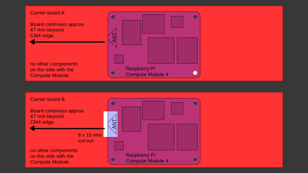
The Raspberry Pi Compute Module 4 has a built-in WiFi antenna, but that doesn’t mean it will work well for you – the physical properties of the carrier board impact your signal quality, too. [Avian] decided to do a straightforward test – measuring WiFi RSSI changes and throughput with a few different carrier boards. It appears that the carriers he used were proprietary, but [Avian] provides sketches of how the CM4 is positioned on these.

There’s two recommendations for making WiFi work well on the CM4 – placing the module’s WiFi antenna at your carrier PCB’s edge, and adding a ground cutout of a specified size under the antenna. [Avian] made tests with three configurations in total – the CMIO4 official carrier board which adheres to both of these rules, carrier board A which adheres to neither, and carrier board B which seems to be a copy of board A with a ground cutout added.

Graph plotting WiFi RSSI for each of the three carriers in each of the six locations. CMIO4 consistently outperforms both, while carrier B outperforms the carrier A, but by a more narrow margin.
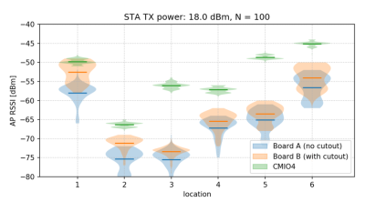
After setting up some test locations and writing a few scripts for ease of testing, [Avian] recorded the experiment data. Having that data plotted, it would seem that, while presence of an under-antenna cutout helps, it doesn’t affect RSSI as much as the module placement does. Of course, there’s way more variables that could affect RSSI results for your own designs – thankfully, the scripts used for logging are available, so you can test your own setups if need be.

If you’re lucky to be able to design with a CM4 in mind and an external antenna isn’t an option for you, this might help in squeezing out a bit more out of your WiFi antenna. [Avian]’s been testing things like these every now and then – a month ago, his ESP8266 GPIO 5V compatibility research led to us having a heated discussion on the topic yet again. It makes sense to stick to the design guidelines if WiFi’s critical for you – after all, even the HDMI interface on Raspberry Pi can make its own WiFi radio malfunction.

Wall Panels With 3760 Antennas Can Increase Wireless Range

Most of us know that to get the best possible WiFi signal, you want there to be as few walls as possible between you and the Access Point. But that might soon change, as researchers at MIT have found a way to make surfaces increase signal strength. Called RFocus, the technique uses a wall panel covered in simple antennas to dynamically focus or reflect RF energy towards a intended receiver.

The normal methods to increase wireless range usually involve increasing the transmitter output or adding larger, more efficient, or directional antennas to the receivers and transmitters. But these techniques are limited when you need to the reduce power consumption and size of the devices. The MIT teams approached the problem from a completely different angle, by optimizing the environment.

The wall panel in question consist of 94 PCBs, each containing 40 passive antenna elements in the form of copper rectangles. Each element is a quarter wavelength long (125 mm for 2.4 Ghz), and on its own it doesn’t have any real effect on the signals, allowing it to pass through the panel. Between the ends of elements are small RF switches, that can close to combine two antenna elements into single half wavelength antenna, creating a reflector. When this is applied across the panel in different patterns it can effectively beamform the signal to focus it at different points in space.

The RF switches are connected to shift registers, which are all controlled via a single SPI bus with an Arduino. Each RF switch is activated in a pseudo-random sequence, changing the configuration of the panel 10,000 times in 100 ms. The signal strength at the receiver is reported to the panel controller for each configuration, allowing the controller to select the best configuration for any single transmitter. In a scenario where multiple low-power sensor nodes are deployed, this can allow the receiver to “focus” on each node in turn. The full paper is a very interesting read, downloadable as a PDF.

RF is generally considered the black magic of electronics, but it can all become a bit clearer with a basic knowledge of antenna theory and modulation schemes.

Thanks to [Qes] for the tip!

PCB Antenna Reference Designs

Have you ever built a wireless project and weren’t sure how to make one of those awesome (and cheap!) PCB antennas? “What low-cost solutions does our Antenna Board #referencedesign contain?” said Texas Instruments (TI) recently via Twitter.  This older reference design contains some comprehensive designs for sub-1 GHz and 2.4 GHz antennas.

While TI’s documentation can be difficult to navigate, there are many hidden gems, and this is one of them. While TI created these designs for use with their wireless products, they will work on any device which utilizes the same wireless base frequency. For example, you could use any of the 2.4 GHz antennas with any Bluetooth, WiFi (2.4 GHz), or Bluetooth Low Energy chips. Simply open up their Antenna Selection Quick Guide document and navigate to the specific design for whichever antenna you would like to build.

For a more detailed overview of what goes into designing and testing a PCB antenna, check out this hack which we featured back in 2010. With the internet of things coming into its own, wireless projects will become more and more prolific, making PCB antennas more important than ever.

DC Entries: LVP/Logic Probe And A Wireless Antenna


I’m sick today, but finally getting some entries up. [Albert] designed this board which can be either a low voltage PIC programmer or, if you lack a programmer to get the initial flash data on the PIC, the through hole components make a logic probe. He rounded out the board with a silk screened logo and a prototyping area. He was also kind enough to provide an eagle library with the Hack-A-Day logo.

Our second featured entry of the day: [Pablo] put together a simple Hack-A-Day 2.4ghz antenna. He built and tested it – It functions nicely as a directional 2db antenna. His proposed use: limit your neighbors access to your AP by aiming the unetched backside at them.