You may have seen the Ruideng range of programmable power supply modules from China: small and relatively inexpensive switch-mode buck converters, with microprocessor control and a front panel featuring a large colour OLED screen. Given 30 volts or so they can supply any lower voltage with the extra bonus of current limiting. They’ve been so successful over the several years they’ve been available that they’ve even spawned their own Chinese clones, and countless hacker projects, for instance on the DPS300X and DPS500X models.
Late last year a new module came from Ruideng, the Riden-branded RD6006 combines the basic idea of the previous modules with an extremely flexible front panel with full keypad and rotary encoder, creating something like the front panel to a decent bench power supply but without the accompanying power supply. I ordered one, waited for it to clear customs, took it to my bench, and reviewed it.
What Does Fifty Dollars Get You As A Power Supply?
It’s well packed in a sturdy box with a foam inner shell, and additionally includes a plug-in temperature sensor, a set of crimp spade terminals, and a spare fuse. I’d ordered the slightly more expensive “W” version with WiFi connectivity, so my £38 ($49) also netted a small plug-in PCB holding an ESP8266 module.
There isn’t a paper manual. Instead there’s a card directing the user to a PDF download on the Ruideng website that yields a document in both Chinese and English which is well written and easy to follow.
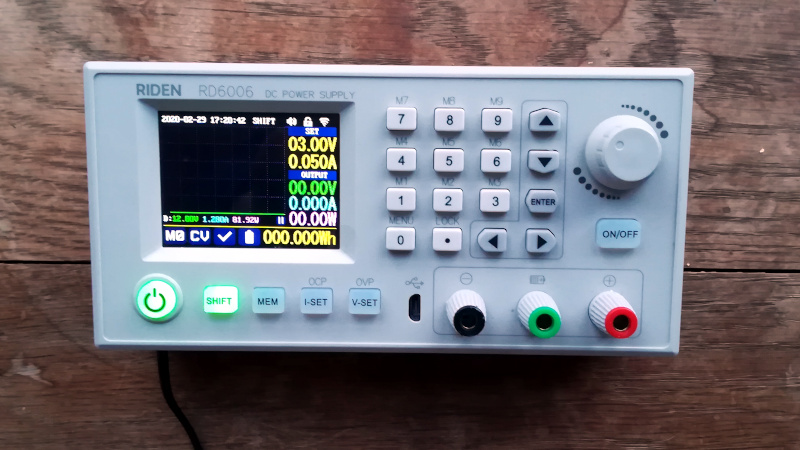
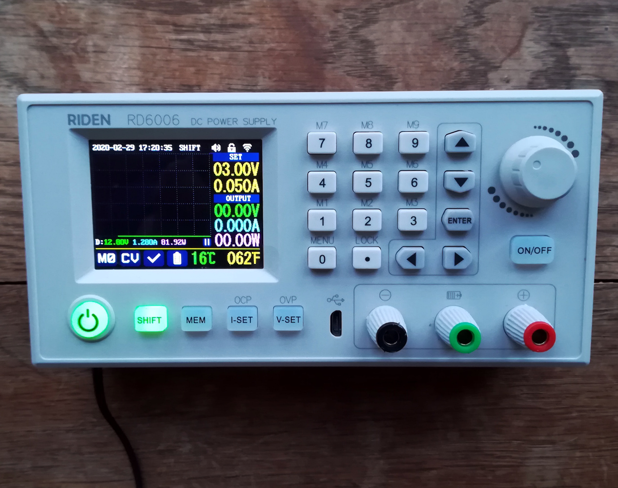
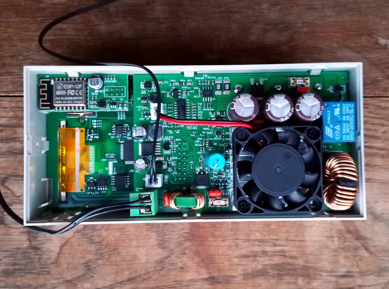
The unit itself is a grey rectangular plastic box around 165 mm x 81 mm (6.5″ x 3.2″) on its front panel, and about 50 mm (2″) deep. The front panel has the complement of buttons and encoder, a 6.25 mm (2.5″) diagonal OLED screen, and a set of output terminals. It’s designed to be a module that sits in a piece of equipment rather than a standalone device, so the rear is not covered and the printed circuit boards are fully accessible. Sockets for temperature sensor and WiFi module are on the left-hand side, and these were easily installed.
Power input is via a set of pluggable screw terminal blocks that can take anything between 6 V and 70 V. I lack a handy 70 V supply, but as will many people with a junk box, I do have a power supply from an HP printer that supplies 32 V at 1.5 A. I hooked it up, and then powered up the unit with its on-off switch.
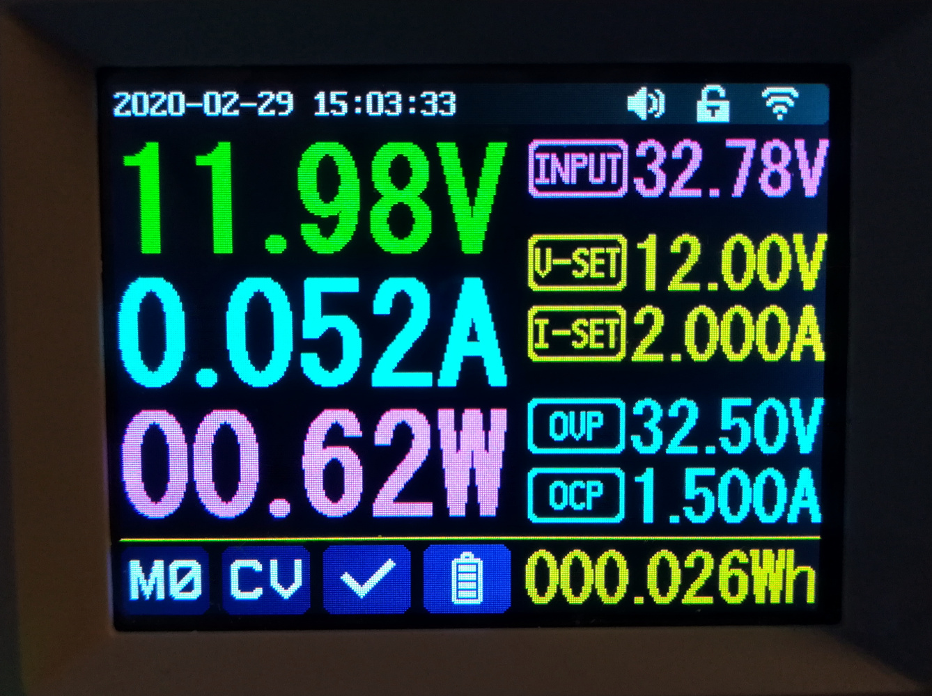
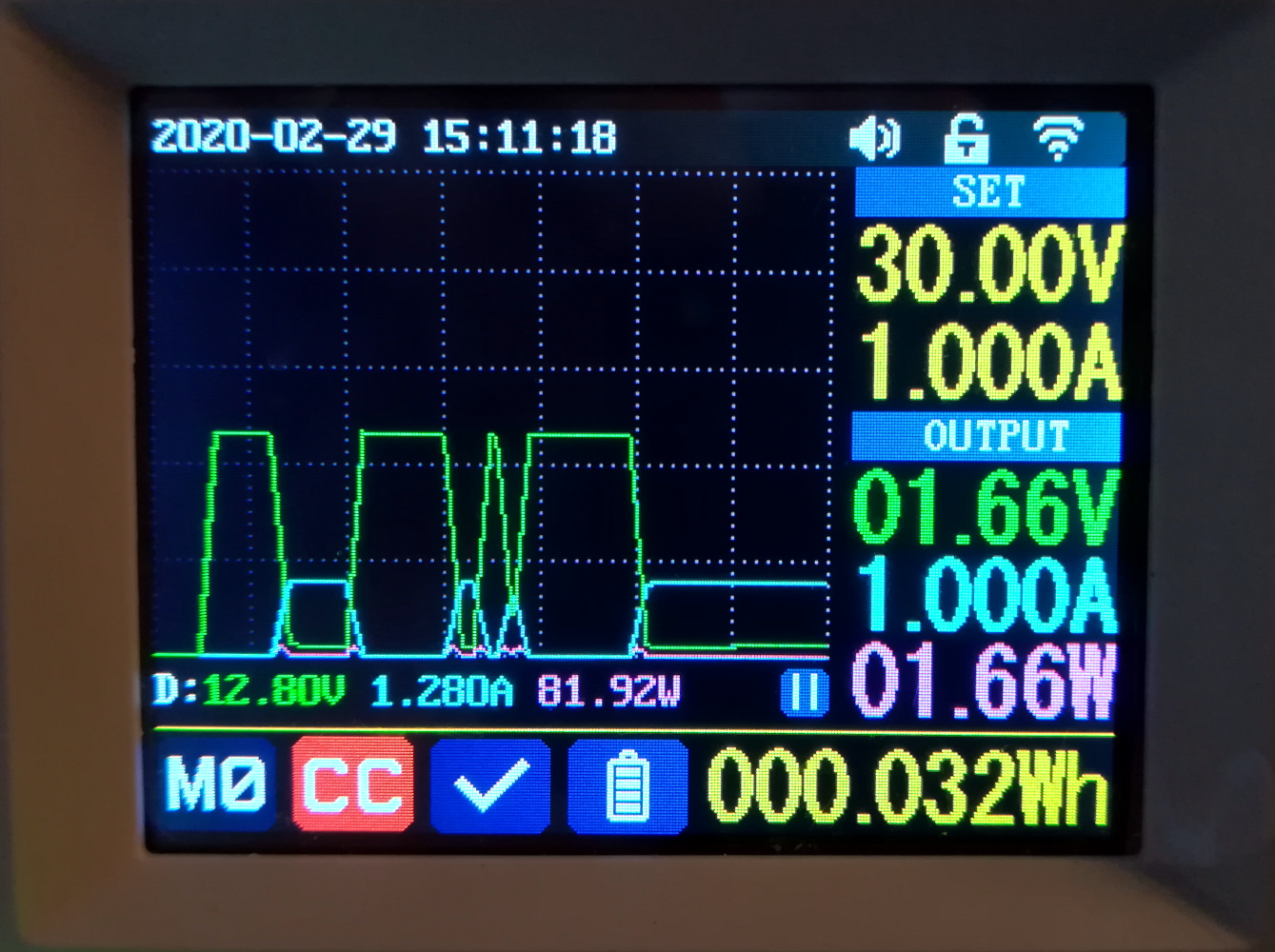
The basic interface will be familiar to anyone who has used one of the previous Ruideng modules. There are three main displays of output voltage, current, and power, and to the right of them a set of smaller displays showing the parameters of the system. Input voltage, output voltage and current limit, and over voltage and current settings are all there, while along the bottom is a temperature display and a set of status flags. To set values there are a set of buttons for selecting which to change, and then a numerical keypad or the rotary encoder to select a value. There is also a battery-backed clock.
What’s It Like In Use?
Beyond the basics the device supports up to nine memory settings for frequently used voltages, and most interestingly, a graphing display option that provides a view of current and voltage over time. The graph can be the default screen, and when it is enabled the input and output voltage and current displays are relegated to the right hand side in a smaller font. It has a flaw though in that it does not appear to automatically update its axes, making it difficult to follow small currents. There did not appear to be a menu option to disable this.
Power output comes from three 4 mm socket/screw terminal combos as you’ll expect from other power supplies. There are the usual positive and negative terminals, with a third terminal between them for a lead-acid battery charging function.
At first glance it’s a capable and easy to use little power supply. Press “V-set” or “I-set” and key in a value, and it’s ready to go. There’s an “On/off” button below the encoder that enables the output; pressing this makes the juice flow. I tested the supply with a variety of loads, from big wirewound resistors to motors, other pieces of electronics, and even shorting a 4 mm cable across it to test the current limiter. As a straight DC power supply in this way it performed faultlessly, never missing a beat and providing measured voltages and currents exactly as it claimed.
There’s a little more to a DC power supply than just DC though, because only the idealised DC from a textbook page is really DC in the frequency domain. All power supplies contain some noise, even batteries, and since the Riden is a switch-mode supply there’s a chance that some of its switching frequency might find its way onto its output terminals. With cheap switch-mode supplies, such as dollar-store phone chargers, this can soemtimes even be visible as a high-frequency ripple on a normal oscilloscope. In the case of the Riden there is no such ripple to be seen.
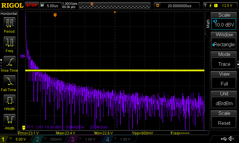
How do you characterise the noise output of a power supply? In this case I think rather than overall noise we should be interested in looking for any peaks at particular frequencies , for example at harmonic multiples of its switching frequency. The only suitable instrument I have is my oscilloscope with its FFT function enabled. It’s a mediocre substitute for a spectrum analyser, but it will quite happily display the harmonics of a square wave used for calibration, so it will serve our purpose here. Hooking the Riden up to a wirewound heating element as a load and applying some volts with my trusty Rigol 1054z attached, I was able to pull up a spectrum of its output. As I would expect there was a broad spectrum of noise but not significantly higher than when connected to a linear supply, and I was pleased to see that there were no obvious peaks even up into the HF range. It seems they’ve done a good job of regulation and filtering, but without better test equipment that’s about as far as we can go.
But This Is The W Version, What’s That All About?
There’s one final part of this review: the WiFi module. It looks suspiciously like an ESP8266-to-serial module that plugs into the main PCB, but how do you use it? In essence it provides connectivity to either an iOS or an Android app. There is an option to enable WiFi connectivity, and then the supply should be restarted in proximity to the mobile phone running the Riden app. At a guess it sets up an access point that the app connects to, you are asked for the credentials of your wireless network, and that’s pretty much it. You can then connect to your power supply with your phone.
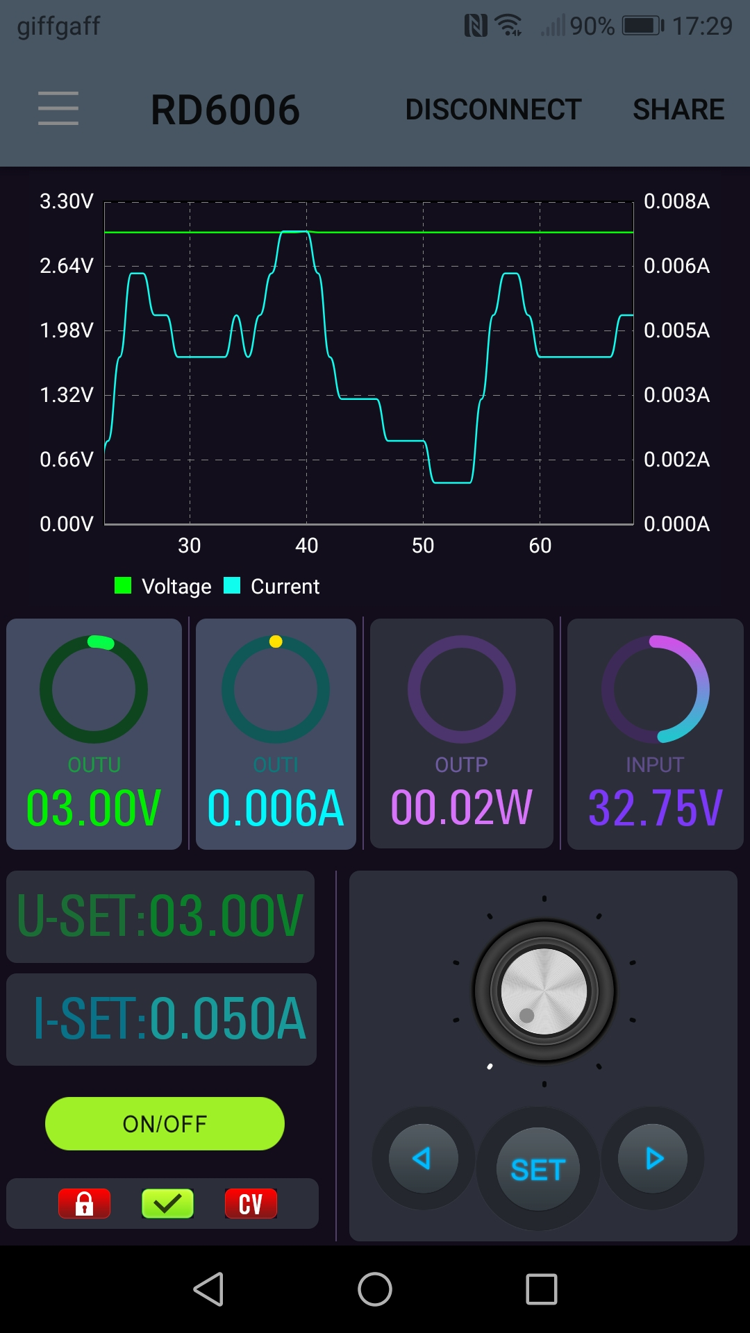
At first sight it simply replicates some of the front panel controls, handy should you ever need to change your current limit from your armchair, but on further inspection there’s a little bit more to it. The graphing function in the app is far superior to that on the device, with axes that scale to the readings in question, and there is the option to save a log of readings. This turns the phone into a powerful extension to the unit, and is in my opinion worth the extra few quid. It’s worth pointing out that in addition to the WiFi there is a USB serial port on the front panel, I’d be extremely disappointed if someone in our wider community doesn’t reverse engineer the APIs involved and produce some open-source software to do more with this facility.
In conclusion, the Riden RD6006(W) seems to follow on from the quality established with the previous Riden modules, and provides a very useful power supply for the price, with plenty of features to keep you occupied. It doesn’t have a mains power supply of its own, so factor that into the price. However, as I found out, there are plenty of readily available supplies that can be used even if they don’t provide the full range of what the unit is capable of. This is well worth considering when you are in search of a power supply.


I have a DPS*** (15A,50V) buck supply module which I use daily. The OLED has a problem that the backlight turns off occasionally. A slight tap with the finger on the display does ‘fix’ it. Other than that the power button membrane has disintegrated.
If the backlight turns off then it’s not OLED, but just LCD.
https://github.com/kanflo/opendps
I tried that and found it barely usable.
It does not even have a decent response time to button presses.
On the bright side, basic functions do work, it’s open source, and plenty of room for improvement.
I hate to be a wet blanket, but is it safe? UL or CE marks? Looking at the photo, I can’t tell whether there’s adequate spacing between the primary and secondary but it looks as if there might not be (usually you see a cut in the PCB).
Oh, never mind…I just saw that this isn’t line powered. Weird, but understandable, I guess.
Does lab equipment usually get UL marks?
Yes, or equivalent, judging by the Fluke, HP, Tektronix, and Agilent gear and am looking at right now.
I wonder how easy it would be to mod the PCB to swap out the diode protected battery charging terminal for earth instead.
Since it’s a buck converter, in principle the negative terminal *is* ground.
That’s the real disadvantage to these units over more expensive ones – it’s not an isolated topology, so negative and ground aren’t different. This means you can’t use the supply for certain things, but personally I haven’t had the need so far.
Ah. If this is anything like the previous DPS PSUs then OCP/OVP is done in software and the current shunt is on the low side.
Since you need to power the unit externally, you’ll very likely power it with a (external) transformer block so it’s isolated. Ground is thus not earth, but nothing prevents you to link the negative to your wall socket’s earth pin if you fear about a floating ground.
It needs a DC input, so the isolation of the – from ground depends entirely on the power supply you feed it with.
Building a PSU around the DPS3005 has been one of those back-burner projects of mine for awhile, but it might make more sense to just get one of these. Though I would certainly print some kind of a back panel for it.
In their store you can buy a case for it that includes space for a 65V “pancake” AC/DC supply you buy from an adjacent AliExpress store. Done this way the whole thing is about US$130.
I ordered this exact kit of parts, but it’s been held up by the whole COVID-19 exercise, unfortunately.
Could you link to what this thing is that you’re talking about? Tried searching for that term but nothing really seems to be right.
Is it this? https://www.aliexpress.com/item/32832089254.html
I’m totally surprised that nobody’s documented the serial protocol yet. Put a tap on the ESP8266 pins and record what goes across.
You could write up a little SCPI interpreter, and this thing could be very very cool.
It uses Modbus like the older DPS PSUs. The register map is different but was worked out shortly after they were released last year. The ESP8266 is just acting as a TCP to serial converter.
But the wireless connection mode is a bit strange. The PSU will connect to the IP of the device used to supply the wireless credentials. I would expect, that I can connect from any device to the PSU as log as the IP of the PSU is reachable.
I would love to see something like OpenDPS for this PSU.
Looking further I find they also do an RS485 module. So there may be some data for that.
That would be my personal preference, even if only to connect that to another RS485 to ttl converter and my own ESP device. I don’t really like having the wireless functionality built in.
I can’t speak for anyone else but I keep and use basic equipment like bench supplies for decades. Consumer wireless standards like WiFi and bluetooth just don’t last long enough. I have several 802.11b WEP devices just waiting for me to take to a recycler. I even have an 802.11 card that predates those and has no encryption at all. Yuck!
I figure that within the lifetime of that bench supply the wireless module inside will become about as useful as those devices are now.
RDTech actually provides the protocol documentation, it’s just buried in one of the software archives they provide for download. I used it to implement a Sigrok driver a good while back.
any chance you could point me in the right direction for this data protocol or anything that will help with the following:
i would like to work out how i can turn my Riden RD6012 on and off from code running on an ATMEGA328P
im not so bothered about programmatically changing any settings, i just want to be able to activate the on/off switch via a microcontroller.
Here’s an simple Arduino compatible library I made a few years ago. There’s a version of the protocol documentation I translated from Chinese there as well. I’ve used it with the DPS and DPH series. I remember looking into these new RD series supplies at some point and think they use the same basic protocol (the functions should work fine). https://github.com/AntaresAdroit/RDTech_PS_Comm
“(the functions should work fine)” actually…. the functions *might* work fine for the RD series is probably more accurate. I just looked around at their RD series documentation and couldn’t find anything about the protocol.
For North America, safety certification (NRTL/SCC/NOM) would be required for the workplace for a device rated for 70Vdc input. Canada import authorities may give you some grief over EMC (ICES-001). For use by a non-commercial private use, ‘certification’ not required by the free nations of North America.
The FFT done for this has very little meaning. A quick and easy test would be to measure PARD using a 50MHz analog scope, or a 200M DSO.
lead acid charging function? seems to be a universal battery charger from the product description.
It is just an integrated diode for that extra terminal.
I feel like they’ve been spying on what I actually use my lab supply for.
I have also bought this PSU. Because I have designed quite many power supplies in my career I was very curious how good is this cheap Chinese power supply. So, I made some load transient test and conductive EMC tests to find out how good is it. As I could expect it doesn’t performs as well as known manufacturer psu which cost about 450€. But differences are actually quite small. Load transient response is not very good. There are under and overshoots. about 300-700mV, depending load ramp. It seems that control loop is not fast enough. This is quite hard to fix without reverse engineering psu schematic.
Then conductive EMC from power output. This kind of psu generates mostly common mode noise, so without real measurement setup you cannot measure psu noise. Scope is not suitable, because it is not sensitive enough and you need LISN to connect measurement device. I made tests using LISN and R&S spectrum analyzer. I also compared results to know manufacturer lab psu. I measured spectrum from 10kHz to 30MHz. There are about 10-20dBuV more noise than the other psu. Switching frequency is clearly visible up to 20MHz. It seems that main cause to this noise is that there is no common mode filter at psu output. When I added common mode choke and capacitors results are even much more better that my other psu. If I have to power analog circuits from this power I definetely use additional filter. Unfortunately it is quite hard to add filter components into psu so external filter is the easiest way to do it.
But overall I am very happy. It performs almost as well as 10 times more costly Thurby Thandard lab psu. So value for money is more that good.
Thank you kind sir for this post and wisdom sharing.
I think you should have done the review…
Personally, I found this more helpful then the article. I’m going to add the filter your describe!
Also Dave from evvblog did a review couple of weeks ago. There’s also a follow up video, because he messed with the probes near the end, bit anyway here’s the first video.
https://youtu.be/0qjLx_HsKUQ
Addition: The DPS series is pretty popular, but Ruideng also has a DPH series. These can also output a higher voltage then iit’s input. Shariariar from the Signal Path has done a review of one of these some time ago.
I own DPS5015, and developed Modbus model of their supply. Not sure if rd6006w conforms to the same protocol though. The model is used to generate C++ API (also reader and writer executables that use the API). If interested: https://boltrobotics.com/article/Modbus-Generate-Ruideng-DPS-Data-Reader/
Jenny:
This isn’t really a power supply. It is really a buck/boost converter. I worked for many years with Hewlett-Packard in their instrument division and worked on many inverters, converters and power supplies. Ours were high quality lab power supplies for the most part.
Having said that I think this is a most interesting little device and I really like your coverage of it. I considering ordering one with the possible idea of connecting it to a solar panel, especially with its lead acid battery port.
Thanks for providing the most useful review.
I’ve had this running on my bench for a while and pretty satisfied with its performance. I’m definitely a novice hobbyist a few months in (posting this for you guys) so my projects atm aren’t very demanding, but so far I haven’t had issues churning out basic IoT and mechanical projects prototyping with this PSU. I remember early on I thought the interface and buttons were a little unintuitive, but a little time and patience cleared that up.
Here’s a vid of me installing it on my bench without having to purchase an additional case: https://vimeo.com/448366906
https://www.amazon.com/USB-WiFi-Constant-Voltage-Current/dp/B08735PVQD
Link to order from Amazon. I am going to use a ATX power supply and house in base of old iMac.
Hello everyone,
I found this via Google. I also have an RIDEN RD6006, but unfortunately, one of its components is damaged, and I’m looking for a replacement part. So far, I’ve only found this German site: https://www.kernel-error.de/2021/03/06/ride-rd6006-und-die-def-schottky-diode-s10c100d/ and the datasheets: https://www.datasheetcatalog.com/datasheets_pdf/S/1/0/C/S10C100D.shtml.
Does anyone have an idea where I can get this S10C100D or what I could use as an alternative?
Thank you!
…so what is the ripple voltage amplitude in your measurements ?