Hardly a person hasn’t experienced the sudden, sharp discharge of static electricity, especially on a crisp winter’s day. It usually requires a touch, though, the classic example being a spark from finger to doorknob after scuffing across the carpet. But how would one measure the electrostatic charge of an object without touching it? Something like this field mill, which is capable of measuring electrostatic charge over a range of several meters, will do the trick.
We confess to not having heard of field mills before, and found [Leo Fernekes]’ video documenting his build to be very instructive. Field mills have applications in meteorology, being used to measure the electrostatic state of the atmosphere from the ground. They’ve also played a role in many a scrubbing of rocket launches, to prevent the missile from getting zapped during launch.
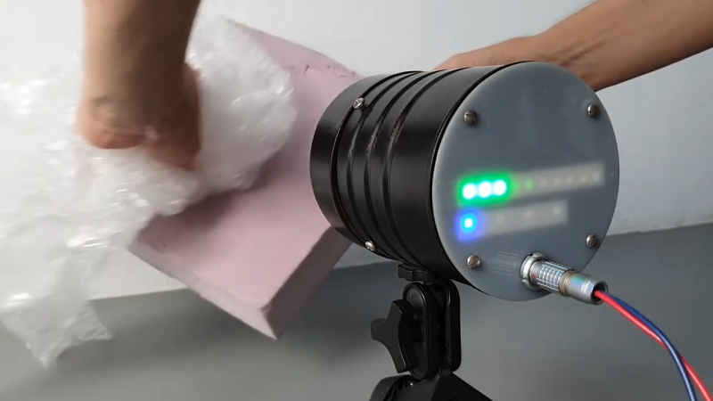
[Leo]’s mill works much like the commercial units: a grounded shutter rotates in front of two disc-shaped electrodes, modulating the capacitance of the system relative to the outside world. The two electrodes are fed into a series of transimpedance amplifiers, which boost the AC signal coming from them. A Hall sensor on the shutter allows sampling of the signal to be synchronized to the rotation of the shutter; this not only generates the interrupts needed to sample the sine wave output of the amplifier at its peaks and troughs, but it also measures whether the electrostatic field is positive or negative. Check out the video below for a great explanation and a good looking build with a junk-bin vibe to it.
Meteorological uses aside, we’d love to see this turned toward any of the dozens of Tesla coil builds we’ve seen. From the tiny to the absurd, this field mill should be able to easily measure any Tesla coil’s output with ease.


I don’t know that you’d be able to use it on a Tesla Coil – Tesla Coils operate at higher frequencies (>50kHz, usually >200 kHz) so the AC would average out when the shutter is open. Standard electrostatic field probes work well with tesla coils and can be calibrated with a suitable DC power supply.
However, a field mill would be great for use with a DC machine like a Van deGraaff or Pelletron or Wimshurst, or, even, maybe a big Kelvin Water Dropper.
Instantaneous or average field? With a frequency many orders of magnitude greater than the chopping frequency, you’ll likely be measuring the average..
The average voltage of a sine wave is zero.
If you sampled fast enough, wouldn’t you just get a modulated AC field?
Take an FFT of the raw output, then demodulate each bin frequency bin individually as if it were an AM radio signal, and you might learn something interesting.
I’m not sure the shutter would be doing anything useful thought, a Tesla coil is going to make so much noise any capacitive “antenna” will pick it up.
A Tesla coil already has its own super fast osculation. No need for a shutter, and no need to find out of its positive or negative. It’s AC… So just measuring the signal on a bare conductor that’s at a safe distance will give you the coil voltage as long as mutual capacitance is known and the time constant of the sensing electrode’s own capacitance and measurement resistance is long compared to the wobble of the coil.
And this will work just great until it breaks out into streamers which will mess up all distances and capacitances.
Apologies for shocking levels of spelling mistakes. Watching a film.
Wow, this is some interesting stuff and very well explained in the video, cool.
Thanks for posting.
I loved this project, beautiful instrument. A few thoughts…
I wonder if a lot of the software complexity (interrupts and such) could be avoided by using the hall pulse to fire a simple sample-and-hold circuit. A sample and hold could be crafted with an op amp, a cap, and a 4066 quad switch.
OP asked for suggestions as to to what to do with this instrument, this is my idea:
Mount the instrument in your back yard, pointed straight up. Connect it to a data logger. I would expect the instrument to respond to the atmospheric charges generated by wind, clouds, rain, and snow. It would be neat to correlate field changes to specific weather events.
I’ve heard that earthquakes are sometimes preceded by changes in atmospheric electricity. Again, it would be very interesting to see if a backyard observatory could record and demonstrate such a correlation.
An application like this would necessarily require a cover of some sort on the open end of the mill. I would suggest a cone or disk fashioned from HDPE cut from an old bleach bottle. HDPE has good dielectric properties and is somewhat UV resistant.
Will the mill work with a cover in place? It might affect the measurement gain, but I suspect it would still work just fine.
Question, how does the dimensions of the electrodes and shutter affect the performance of the instrument. Suppose I were to build a mill 3 feet in diameter?
Another question…perhaps I missed this, but how was the device calibrated?
For someone with a software background, sample and holds are probably going to be way harder to build, plus they add more analog parts which makes the insides harder to do neatly.
It’s amazing how perspective changes everything! I’d gladly add 100 lines of code to save a few passives or a transistor, but to someone with an analog background, it seems to be the opposite!
Pointing the field mill down is actually way easier, and is how people who use field mills day to day do it. You get the same results more or less, just calibrate it.
Interesting bit about doing things more analog. I work in a group that is building a field mill which we plan on sending to the moon, that is several orders of magnitude more accurate than this one. We get away with just an ATmega128 doing all the demodulation. We experimented with an analog solution using analog multipliers and low-pass filters, but quickly found that to be too fiddly. We’re working on a paper explaining how it works.
I would not put anything in front of the mill, especially not an insulator. It will get charged and mess up your measurement. It’s really hard to zero these things, a problem that was noticed by Ross Gunn back in the 1930’s.
To the moon. That’s pretty neat. What’s the scientific hypothesis you’re testing? Do you have a URL explaining it more?
Testing testing
(ok now I figured it out, I had an issue with the referrer header)
I sneakily left a link in my name but I guess there’s no harm in reposting it: https://www.spacesciencesweden.se/ The site’s a bit short on info, but has some relevant link. The server we had the previous site on has gone down, but archive.org has copies of it. I have the disk, but I haven’t bothered setting it back up yet.
The short of the mission is that we want to investigate how the solar wind interacts with the dusty plasma that surrounds the lunar surface. We especially want to measure how fast the electric field changes at the terminators (sunset and sunrise). It is suspected that the change in the sign of the electric field launches dust high up into the lunar “atmosphere”. The “streamers” seen by the Apollo astronauts is thought to be this dust being levitated/launched by the change in the electric field.
One challenge is that the electric field is thought to be quite weak, on the order of +-10 V/m. [Leo] states that his device is accurate to about 1 kV/m. State of the art field mills can manage roughly 20 V/m accuracy. Our device improves on this considerably. We are currently running long-term stability tests to determine just how much better it is.
Ah. Excellent. Very interesting. Thanks for the followup, and best of luck with your instrument.
Woah. Deja vu. I remember this from Shawn Carlson’s Scientific American column from around 1999. I still have the paper version right here somewhere.
It seems it would detect charges in a 180° field in front. I wonder how to narrow that field. Perhaps extending the steel housing forward?
The sensing plate(s) just sense the local electric field potential. That’s all. “Field of view” is meaningless here. Extending a shield forward to sense through a tunnel-like structure would just reduce the amplitude.
Electric field obeys superposition, so there’s no way to narrow the field of view. In theory the device will show the same value no matter the direction or aperture (noting that the signal is proportional to the cosine of the area of intercepted incident field so there will be variation due to angle, and smaller aperture will reduce the incident field but not introduce directivity).
On that last point, he could add orientation-sensing to measure the direction of the electric field (direction of maximum intercept, where cos of angle is zero), and he can move the *position* of the device to get electric field over an area. Electric field lines can curve, so the direction of maximum field strength (where cos of angle relative to sensor is zero) may not be the straight-line direction to the charge source.
Measuring the electric field of the ground might prove interesting – mount several devices across a push-wheel device (like a seed spreader or old-fashioned lawn clipper) with direction sensing and wheel distance sensing. That would make a “map” of electric field along the ground, and might turn up buried pipes, wires, or other objects.
In theory you could substitute the mechanical shutter for an electromagnetic one. Adding a cowl and making it smaller you could have an array and get directional information.
Can you describe how such an “electromagnetic shutter” will work? I can’t figure out how it possibly could.
Suppose the shutter cover were stationary over the sensor. When grounded, it acts like the moving shutter in the article. When allowed to float, electric field lines should pass through the floating potential of the conductor to the sensor.
When the conductor is floating the incident field lines cannot end in the conductor but have to float through it to the sensor. In the grounded case the field lines enter the conductor but are routed around the sensor to exit from another location.
Heck, if you commutate the cover, letting it float to the ambient potential and then back to ground, why bother with a separate sense electrode? Just measure the AC current in the switch that does the commutation. Or measure the potential shift on the cover directly.
Then, figure out why that won’t work.
Go try that and report back, you seem to know all about physics and have the necessary skillz.
If you put an ungrounded conducting plate in an electric field, a charge is induced on it so the electrons move in the plate. Say it is a negative voltage on the bottom of a cloud. Electrons in the floating plate move to the bottom of the plate. The overall charge of the plate is neutral, but it is now positively charged on top, negatively charged on the bottom.
So far, so good.
Now momentarily ground the plate. Electrons rush out into ground, leaving an overall positive charge on the plate, but the bottom is now neutral (assuming the Earth is the ground as an infinite charge sink).
Unground it. It still has an overall positive charge with the bottom being neutral. So any device under the plate, after the first grounding, will see no net electric field.
https://www.brainkart.com/article/Electrostatic-induction_529/
Combine this with the inverse Radon transform and you could image the distribution of electric charge.
Doing that with a thunder storm would be educational.
Radon transform implies you’re sensing in a well-defined direction. A field sensor like this measures just the field amplitude at the location of the sensing electrode (relative to its occluding shutter = voltage reference). It’s a single point measurement with no directionality. You couldn’t create an image of a charge distribution even if you covered 4pi around it. The problem is too ill-posed to form a solution (at least not a unique solution).
You could have three sensors in a triangle out in a field, and perform correlation measurements between the three of them. Changes in electric field propagate at the speed of light, so a pulse would arrive at different times.
From the cross correlation and changes in relative phase of the correlated signal across the sensors you could plot the location of the pulse emitter and how that position changes over time.
You might be able to plot the course of a lightning bolt as it travels through clouds and then down to the ground.
With sufficient bandwidth that would be an interesting thing to do, but would be easy enough with a few monopoles on AM radio receivers: no field mill required. This thing, as built, has a bandwidth of at most a few dozen Hz: sufficient to resolve continent-scale electromagnetic events (once you get the detectors that far apart and synchronized), but certainly not a local thunderstorm.
Pointing the field mill down is actually way easier, and is how people who use field mills day to day do it. You get the same results more or less, just calibrate it.
Interesting bit about doing things more analog. I work in a group that is building a field mill which we plan on sending to the moon, that is several orders of magnitude more accurate than this one. We get away with just an ATmega128 doing all the demodulation. We experimented with an analog solution using analog multipliers and low-pass filters, but quickly found that to be too fiddly. We’re working on a paper explaining how it works.
I would not put anything in front of the mill, especially not an insulator. It will get charged and mess up your measurement. It’s really hard to zero these things, a problem that was noticed by Ross Gunn back in the 1930’s.
Neat build. I want one. One thing you may want to clarify in the video though is the X1, X10, and X100 on the paper, they are the ranges, which are the inverse of the amplification factor. Also I am just curious in your auto ranging scheme, do you start with the lowest range first and do a simple if than to see if you need to kick down to the next one? It seems easier to work down from the most sensitive to the least.
Hey, would you mind walking me through what you mean by ranges? Trying to build one and currently working on the op amp stage.
I sneakily left a link in my name but I guess there’s no harm in reposting it: https://www.spacesciencesweden.se/ The site’s a bit short on info, but has some relevant link. The server we had the previous site on has gone down, but archive.org has copies of it. I have the disk, but I haven’t bothered setting it back up yet.
The short of the mission is that we want to investigate how the solar wind interacts with the dusty plasma that surrounds the lunar surface. We especially want to measure how fast the electric field changes at the terminators (sunset and sunrise). It is suspected that the change in the sign of the electric field launches dust high up into the lunar “atmosphere”. The “streamers” seen by the Apollo astronauts is thought to be this dust being levitated/launched by the change in the electric field.
One challenge is that the electric field is thought to be quite weak, on the order of +-10 V/m. [Leo] states that his device is accurate to about 1 kV/m. State of the art field mills can manage roughly 20 V/m accuracy. Our device improves on this considerably. We are currently running long-term stability tests to determine just how much better it is.
(reposting my comment since it ended up at the bottom of this post instead of as a reply to this comment)
I sneakily left a link in my name but I guess there’s no harm in reposting it: https://www.spacesciencesweden.se/ The site’s a bit short on info, but has some relevant link. The server we had the previous site on has gone down, but archive.org has copies of it. I have the disk, but I haven’t bothered setting it back up yet.
The short of the mission is that we want to investigate how the solar wind interacts with the dusty plasma that surrounds the lunar surface. We especially want to measure how fast the electric field changes at the terminators (sunset and sunrise). It is suspected that the change in the sign of the electric field launches dust high up into the lunar “atmosphere”. The “streamers” seen by the Apollo astronauts is thought to be this dust being levitated/launched by the change in the electric field.
One challenge is that the electric field is thought to be quite weak, on the order of +-10 V/m. [Leo] states that his device is accurate to about 1 kV/m. State of the art field mills can manage roughly 20 V/m accuracy. Our device improves on this considerably. We are currently running long-term stability tests to determine just how much better it is.
Which transimpedance op amps did you use?