It isn’t hard to imagine a scenario where you are stuck at home all day with nothing to do and certain items are in short supply. Sure, bathroom tissue gets all the press, but try buying some flour or a freezer and see how far you get. Plus online shopping has given up on next day delivery for the duration. Not hard to imagine at all. Now suppose your latest self-quarantine project needs a rotary shaft encoder. Not having one, what do you do? If you are [Tech Build] you go all MacGyver on an old printer and pull out a stepper motor.
How does a stepper motor turn into an encoder? Well, that’s the MacGyver part. We are not big fans of the physical circuit diagrams, but it looks like [Tech Build] borrowed (with credit) from an earlier post and that one has a proper schematic.
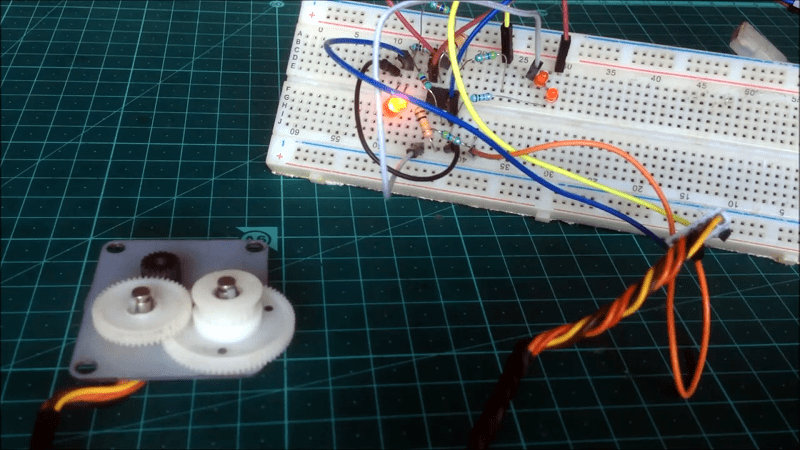
Looking at [Andriyf1’s] schematic, you can see each coil connects to an op-amp wired as a positive feedback comparator. The result should be a fairly clean square wave from a noisy input. The real trick is how to connect the coils, which depends on how the stepper is wired. If you have a stepper motor of unknown provenance, grab your ohmmeter and read how to sort the wires out.
The initial version was on a breadboard, but the final was on a prototyping board. Of course, an Arduino reads the pulses. We love using things for unintended purposes. Speakers and microphones are often interchangeable. Generators and motors, too. Then there’s the paperclip.


Has there been a version of this where you could still drive the stepper as a motor normally and also get position data, functioning as a sensor that also provides haptic feedback? Like some kind of inductance measurement on the coils. I seem to remember seeing that somewhere.
Huh?
Whatever drives the stepper motor can keep track of the number of steps, and direction. No need for feedback.
As an encoder, a stepper motor has nothing absolute. There is no stop, no indicator of position, you have to count steps and direction to give a sense of anything. As a motor, it works tge same way.
Flopoy drives stepped the head across tracks. But the only absolute was track 0, because there was a separate sensor in the drive. So all that’s was needed was to step until that sensor went high, at which point you knew where you were.
“But the only absolute was track 0, because there was a separate sensor in the drive. ”
Unless you had a drive without said sensor, like the drive for the Apple ][ – the software just kept track of where the head was. At boot time, in order to start at a known track, the drive would be told to step the max number of tracks towards zero which almost always lead to a grinding sound – that was the head hitting the track 0 physical stop but the bios didn’t know that because there was no sensor. This wasn’t a bug – it was a cost-saving feature. :-)
That sounds like a simple end stop sensor (a switch), and not sensing in the stepper motor.
But it wasn’t, it moved the maximum of 40 tracks blindly and hit a rubber stopper multiple times if it was actually closer than that.
http://apple2.org.za/gswv/a2zine/GS.WorldView/Resources/DOS.3.3.ANATOMY/BOOT.PROCESS.txt
Huh?
Whatever drives the stepper motor can keep track of the number of steps, and direction, assuming the driven thing won’t slip, especially when microstepping. My first CNC was unable to keep track of the position because steppers and drivers were underpowered, while the mass they moved was too great. I usually lost 10-50 steps per movement on average. Then I increased the voltage for the drivers and set the current properly. Still, if the sum of resistance caused by mass of the head, resistance caused by the mill milling the material and the sum of both mechanical resistance of drivetrain and indentations of stepper were greater than driving force of the stepper, supply and driver, the controller would loose the count as steps that should be taken would not be taken. Also every time stepper changes direction, there is added error of magnetizing and demagnetizing of the stator, which can cause some steps to be not made. You can’t be sure that stepper made a step, especially a microstep, unless your stepper and driver are seriously overpowered.
And even your new machine works perfectly and keeps track of steps without feedback, it will stop working properly as soon as enough dirt accumulates in the drive train to overcome steppers.
This is a common problem in the world of CNC…
Yeah, my first thought when I saw this was oh wow a pseudo closed loop stepper, so my mill can shut down when there’s a crash!
Your kidding, right? Or have you actually never heard of a stepper missing steps?
Feedback would be useful I think, when ramping up the motor instead of relying on blind timing you could detect when it has actually reached the next ‘checkpoint’ – maybe could even detect when the motor has missed a step. I think with varying loads this would be very useful.
Thinking out loud: You might be able to under-drive a stepper motor using a driver with stall-detect, and alternate single-stepping (or similarly-low step-count) it back and forth. The stall-detect would trigger on the resisting force, giving you a haptic/force feedback mechanism of sorts.
I think you’re talking about TMC2130’s StallGuard or something similar? Though it might be the exact opposite of what you’re saying. It detects when the motor misses a step, so you can use it as a virtual endstop on 3d printers
I had a project about that, but it was a PMSM (or BLDC) motor and it didn’t work normally. No significant torque, only a little to create the haptic feedback. But it has the advantage of working at zero speed. The method is probably compatible with steppers, but I didn’t try.
https://hackaday.io/project/160585-motor-as-encoder
Quick question: what has macgyver to do with another derivative of what has been done and written about many times before?
I have a feeling even had has written about this at least once before, but I can’t be bothered looking it up (with that wrap-around search of yours).
Steppers of unknown providence? Mom always told me to never accept steppers from strange gods.
Did you mean “provenance”?
That cracked me up at 6 am.
Imagine needing to buy steppers instead of just getting them from random gods, smh.
I while back I was looking for really high res encoders, and one of the options i came across which is pretty intresting was to use a brushless DC motor. You can read each phase with a dac and then interpolate each sin wave by the number of bits in a dac for example 3 phases with 12 bit dacs would give 3×4096 bits of data per sin wave pretty intresting stuff, but it turns out for 10 bucks you can buy magnetic encoder chips that have 100,000s of steps using a two pole magnet which is a much easier way to go.
I wonder if you could use some sort of sensor attached to the motor to let you know where “start” is? Several options, but my mind is stuck on magnetic right now, so maybe a reed switch and a magnet. When the switch reads high, you know you are over the magnet. You could get more precise, with some sort of optical thing, but you get my drift. What if you had several placed around the motor and you could know if you were at point A, B, C….. Would that be handy? Once you had the start point, you could know where the motor is pointing, or turning, i guess. Just an idea.
Look in to melexis 90217 it’s a simple sensor designed exactly for what your describing. You couldn’t use it to distinguish between multiple unique points, but using it along with data generated by to motors poles it can be used to find absolute position In reference to the shaft angle of the melexis 90217
maybe a silly question, but has anyone seen such setup used for a ‘dj-like’ turntable ? ( when the motor would move freely & be used as a sensor when a plate on it was touched, and then have it back moving to some 33/55 rpm when no longer touched ). I was actually looking for such stuff few days ago
A lot of stage light devices and DMX consoles used stepper motors as encoders in 90s. It was very common solution, due to outstanding reliability and very nice haptic feedback.
The encoder and motor doesn’t need to be the same device. A weak motor can slip and let you move it. The encoder could simply be strips printed on a sticker for reflective optical sensor.
You can use 2 concentric circle of strips spaced 180 degrees if you want to sense both direction and number of steps like the mechanical mouse.
Hi folks and welcome back to another edition of RW’s dumb idea of the day: In today’s episode we ponder the idea of using a vernier type system, with a power of 2 resistor network feeding an analog input on your micro flavor of the day, to detect position with 10x more accuracy, over to you peanut gallery…
(Yah, I’m not sure if it’s a resistance wiper, electro optic based on shading/hatching or what right now, it’s near bedtime)
The current trend with many new moving lights is to hang a magnet on the unused shaft side and a hall effect sensor so that every full shaft rotation gets a home position feedback. Besides detecting lossed steps, it allows the fixture to “home” quicker by not having to run all the way to an end stop.
The ETC Microvision light board (mid 1990’s) used a stepper as the encorder for the “wheel” It worked ok…unless you spun it too fast…then it tended to think it was spinning the opposite direction
I bookmarked this in 2001:
https://web.archive.org/web/20010610053855/http://members.iinet.net.au/~richardh/Rotenc.htm
Is it possible to do this with a simpler amplifier circuit? Like maybe something that is just a couple of bipolar transistors and a few passives or something like that?
No, I’m not trying to “could’a done that with a 555” this post. It’s just that if I were to use such a trick it would be because I was trying to stick with the sorts of parts I keep on hand in quantity in the junk box. I do keep a few op-amp chips but bags of common transistors.
Mess around with this then… https://www.psaudio.com/pauls-posts/being-discrete/
Probably you can do it without the 2 drivers, just the front end, since we’re talking of just outputting a square wave, logic level, not trying to drive anything.