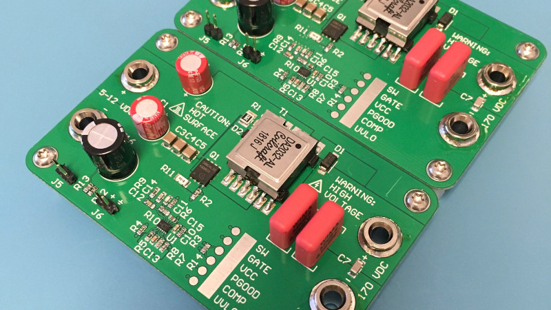
It is tempting to think of analogue and digital domains as entirely distinct, never to touch each other except like a cold war Checkpoint Charlie, through the medium of an ADC or DAC. In reality there are plenty of analogue effects upon digital circuitry which designers must be aware of, but there is one field in which the analogue and the digital are intricately meshed. Switch mode power supplies use digital techniques to exploit the analogue properties of components such as inductors and capacitors, and can be astoundingly clever in the way they do this to extract the last fraction of a percent efficiency from their conversion. Thus their design can be something of a Dark Art, so it’s always interesting to have a good read explaining some of the intricacies. [James Wilson] has built a flyback step-up converter to power Nixie tubes, and his write-up follows the whole process in great depth.
This type of converter seems at first glance to be a simple step-up design with a transformer that has a primary and secondary, where in fact it relies on the collapse in magnetic field during the off period of its duty cycle to provide a spike in voltage and thus a step-up beyond that you’d expect from the transformer alone. The write-up takes us through all this starting from a theoretical perspective, and then goes further into the realm of component selection and the effects of component properties on the waveforms involved. If you have ever battled ringing in a switch mode power supply you may recognise some of this.
If this field interests you, then there is probably no better place to send you for a start than Jim Williams’ 1987 app note 25 for Linear Technology: “Switching Regulators for Poets“.


We need an hero to desing a flyback converter for CRT Tubes.
Is that not how the flyback transformers in all mature CRT technology works? I don’t think the transformers in those reach such a high conversion ratio by the number of coils alone. I was under the impression that some field-collapse dynamics was involved just like in an ignition coil in a car, which was at first switched by primitive mechanical points (never the case in a tv) and later by fairly basic active electronic components.
Flyback transformer is a bit of a misnomer.
A (normal) voltage transformer uses in phase voltage conversion though direct energy coupling between primary and secondary. The secondary voltage being a product of the primary voltage and turns ratio. The primary drive is sensitive to the secondary load as it’s transferring power.
An impedance transformer (balun) is much the same.
A flyback transformer is more like two magnetically coupled inductors. The primary inductor must store enough energy into the former for the secondary requirements however the primary inductor does not drive the secondary as the secondary passes current to the load when the primary is off. The secondary voltage is not a result of turns ratio. Instead it is derived from the back EMF of the collapsing magnetic field in the secondary inductor.
You can put a tv-line frequency pwm on the primary coil (300v or so) of a TV flyback transformer and use one of the other coils for regulation feedback. The hv regulation will not be very precise but doesn’t need to be.
Heck, maybe while he’s at it, he could design a flyback converter that opens a set of contacts to generate a high-voltage pulse to trigger ignition in an internal combustion engine.
If you really want to confuse people, design a synth using nand gate oscillators and inverter/buffers as op-amps, boards full of “digital’ chips in analog mode.
And not just audio frequencies.
You can get very high frequencies from 74HCxx chips.
Then you can mix both analogue and digital modulation demodulation techniques.
Extra points for using one gate for both analogue (linear) and digital modulation demodulation at the same time.
And RF frequencies with ECL gates.
“but it appears the efficiency of the transformer is the limiting factor”
No. Transformer coupling, leakage, etc are important factors, but unless your switching freq is wrong, transformer ‘efficiency’ is not the main contributor to losses in a flyback converter.
Low voltage input and output conditions for SMPS are always the least efficient; and flybacks tend to be less efficient than other topologies.
Strongly recommend the Pressman book on SMPS design.
Perhaps that was not the best way of phrasing it but the core losses were very high at this switching frequency and when I brought it down from 350 kHz to 100 kHz this converter would run at 88-90% efficiency.
For powering Nexie, you don’t really need a flyback. You can get by with a boost converter. It only gets tricky when you want beyond 1:10 boost ratios. I used a boost converter for mine with a voltage doubler which removes that requirement.
Heh, does anyone remember messing with HV in the 80s and 90s and you’d come up against an “expert” who’d tell you that it’s really easy “All you need is a Ford Model T spark coil and a buzzer”…. and you’d be pissed off because even sufficiently robust electromechanical buzzers were tricky to find new then, and nobody had regarded a Model T spark coil as an easy to find or cheap part for 20 years.
Well, my first experiences with HV were with a relay wired as “vibration step-up converter”. It didn’t generate very high voltages, but it was ‘shockingly’ funny. Not that everyone I shocked was glad of it.