Is your heaving pile of electronic parts shrinking by the day as you finish old back-burnered projects and come up with new ones? Try an old pastime that never gets old: rolling your own sensors using household objects. [Nematic!] needs a way to sense vibration for an upcoming project. Instead of spending $1 plus shipping and waiting who knows how long for a spring vibration sensor to come in the mail, they made one in a matter of minutes.
A spring vibration sensor is a simple device that can be used as a poor man’s accelerometer, or simply to detect vibration. All you need is a length of conductive wire, a 10 kΩ resistor, and a way to pick up those good vibrations. For the purposes of demonstration, [Nematic!] is using an Arduino Nano in the short build video after the break.
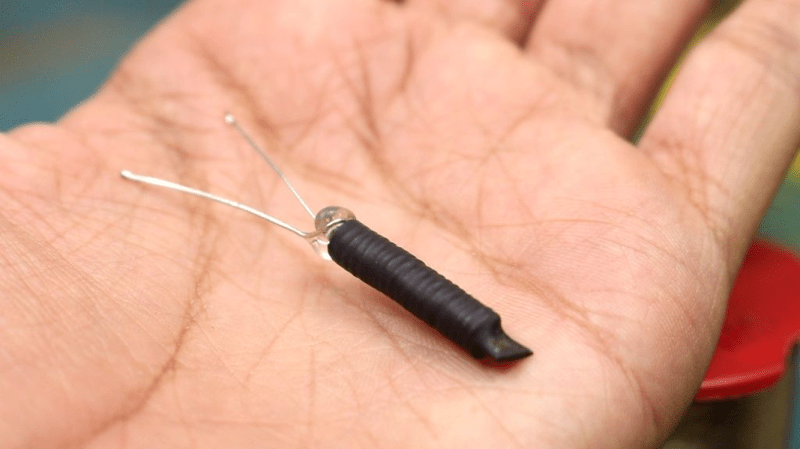
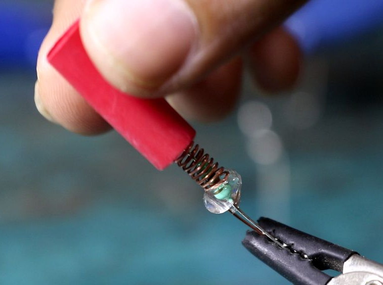 The wire is wound around the threads of a bolt to form a coil that’s just large enough for a resistor to fit inside. One end of the coil is connected to 5 V, and one leg of the resistor connects to an input pin. Together, they form a normally-open switch. When vibrations force the free ends of both to touch, the circuit is complete and the pin is pulled high.
If you make one of these and find the sensitivity is off, just twist up a new coil with stiffer or softer wire depending on the problem. Iterating doesn’t get much cheaper than wrapping wire around a bolt. We can’t wait to see how [Nematic!] will use this sensor. In the meantime, we’re planning to use one to detect when the dryer stops running and send a text.
Speaking of bargain basement sensors, did you know you can detect water leaks with two pennies, an aspirin, and a clothespin? These projects demonstrate the kind of ingenuity that can win you a pile of toys in our new Making Tech At Home contest, running now through July 28th, 2020.


Seems like the heatshrink would drastically reduce the sensor’s sensitivity.
Maybe that’s the idea…
So 70’s car alarm shaker switches are gonna make a come back?
1.) I think that spring inside metal tube will be more reliable and less succeptible to permanent deformation.
2.) Arduino has no internal pulldown resistor, so it’s bad idea to use this sensor for connecting arduino input to 5V. It can remain charged for a while after triggering or even pickup EM noise (this happens VERY often). Use sensor to connect pin to the ground instead. And do not use series resistor (the one inside the coil in the video) unless you have carefully calculated it to work with internal pullup.
AVR in era of more reliable, faster, cheaper and smaller microcontroller itself bad idea, unless you’re already have it and there’s not possible get a decent an one for requested time/budget.
Also if DIY whole point why not make for yourself semiconductor too? https://hackaday.com/2017/02/25/the-fab-lab-next-door-diy-semiconductors/
AVR still are reliable, small and cheap.
What’s the issue with these?
Overpriced in comparison with an one of those “<$0.05" microcontroller.
Underpowered in comparison with those of same price category.
Pretty old manufacturing process so low Perf./W and huge heat dissipation requirement(for microcontroller).
Only low ( like 25v with expensive mega) voltage operation.
Nice to see a project like this. Thanks.
Due to exposure to air and mosture, the copper will oxidize quicky and the sensor will be useless.
As someone already said it, being covered in shrink tube most of the sensitivity goes away. Basically the resistor free terminal becomes the sensor, so you can use any metal tube instead of the coil.
Perhaps better is to put it into a small glass container (like small vials used for rom and vanilla essences) with inert gas (like CO2) and isolated as much as possible (epoxy, not hot glue).