We are all used to the op-amp, as a little black box from which we can derive an astonishingly useful range of circuit functions. But of course within it lurks a transistor circuit on a chip, and understanding the operation of that circuit can give us insights into the op-amp itself. It’s a subject [IMSAI Guy] has tackled during the lockdown, recording a set of videos explaining a simple discrete-component op-amp.
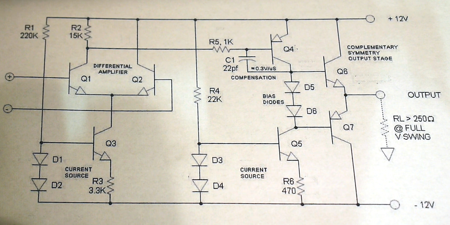
He starts with the current source, a simple circuit of two diodes, a resistor, and a transistor that sets the bias for the two-transistor differential amplifier. This is followed by a look at the output driver, and we would expect that shortly to come will be a video on the output itself. Start the series with the first episode, which we’ve placed below the break.
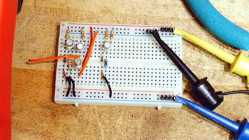
His style is laid-back, making it a restful watch as he builds each circuit on a breadboard and explains its operation with the aid of a multimeter. If this whets your appetite for more on simple op-amps, we looked at the first integrated circuit op-amp back in 2018.
Thanks [IanS] for the tip!


CA-3086 & some external components was the way we did this project back in the 1980s
I will watch these videos, but as many people have discovered, it is hard beat an integrated op amp. The matching of the components is much tighter, the thermal matching is unparalleled. One of those things where going discrete sounds like a great idea but the usually don’t work out as well as their integrated counterparts.
I think the point is more about learning about the internal workings, not trying to surpass or match the IC version.
It teaches some generally useful transistor circuits that help understanding circuits in general.
+1 😀
For sure, and I do intend to watch the video, it was more of an aside that the integrated ones have grown to be the nicer ones now. I have some early discrete potted ones kicking around in something. Back in the day when the discrete ones could outperform the integrated ones.
+1
I think at least getting a handle on constant current sinks and sources and current mirrors is very worthwhile.
I’m amazed how often this needs to be pointed out here.
Understanding the basic differential pair is useful because it allows you to whip up a simple comparator out of two transistors and one resistor. It won’t have ultimate precision, but often will do the job just nicely.
Around 73 or 75 Radio Electronics had an article about making your own op-amp from discrete components, but I can’t remember anything specific enough to find the issue.
It wasn’t a tutorial, but a project. Op-amps generally had limitations, so building from discrete parts at the time had advantages. These were intended for better audio use, it was a time offlots of audio building.
Ah yes. Great stuff.
If you need custom op amp, this is it.
For example one that works at 100 V …
If you can live with common mode range of a regular opamp, you could add a high voltage output stage.
Most of the tricky stuff: input DC voltage/current offset, input impedance, gain are best left to the chip level component matching etc.
There is a specialty op-amp for that :)
https://www.analog.com/en/products/ADHV4702-1.html
Yup, you can wack the 2nd stage amplifier and output stage of this example op-amp onto most any IC amp to get 100’s of volt swing. Did this with an LMC662 on a photo-diode amplifier. Got 60fA rms noise and could measure several nA of photo-current.
Can also be great when you want custom input properties. Like fA bias currents or low voltage noise combined with low current noise. No IC’s going to run >100mA through the input FET to drop noise but you sure can.
I have a K2-W Philbrick vacuum tube op amp if you really want to get primitive and learn about them. Would take a Widlar 709 any day over a discrete.
As it happens, my very first paid job (between school and university) started by evaluating the uA741 as a possible replacement for the uA709.
OMG! No compensation cap. Are they CRAZY?
I made one of these in Uni, great learning experience. Current sources, current mirrors, output stages etc. Lacked the output current limiters common in IC Opamps, though ;-)