Batteries are notoriously difficult pieces of technology to deal with reliably. They often need specific temperatures, charge rates, can’t tolerate physical shocks or damage, and can fail catastrophically if all of their finicky needs aren’t met. And, adding insult to injury, for many chemistries, the voltage does not correlate to state of charge in meaningful ways. Battery testers take many efforts to mitigate these challenges, but often miss the mark for those who need high fidelity in their measurements. For that reason, [LiamTronix] built their own.
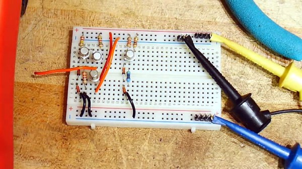
The main problem with the cheaper battery testers, at least for [LiamTronix]’s use cases, is that he has plenty of batteries that are too large to practically test on the low-current devices, or which have internal battery management systems (BMS) which can’t connect to these testers. The first circuit he built to help solve these issues is based on a shunt resistor, which lets a smaller IC chip monitor a much larger current by looking at voltage drop across a resistor with a small resistance value. The Pi uses a Python script which monitors the current draw over the course of the test and outputs the result on a handy graph.
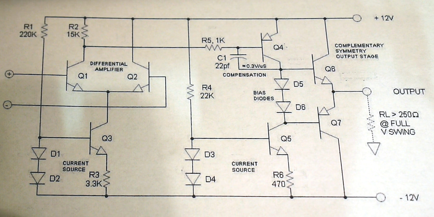
This circuit worked well enough for smaller batteries, but for his larger batteries like the 72V one he built for his electric tractor, these methods could draw far too much power to be safe. So from there he built a much more robust circuit which uses four MOSFETs as part of four constant current sources to sink and measure the current from the battery. A Pi Zero monitors the voltage and current from the battery, and also turns on some fans pointed at the MOSFETs’ heat sink to keep them from overheating. The system can be configured to work for different batteries and different current draw rates, making it much more capable than anything off the shelf.
Continue reading “Battery Tester Outperforms Cheaper Options”