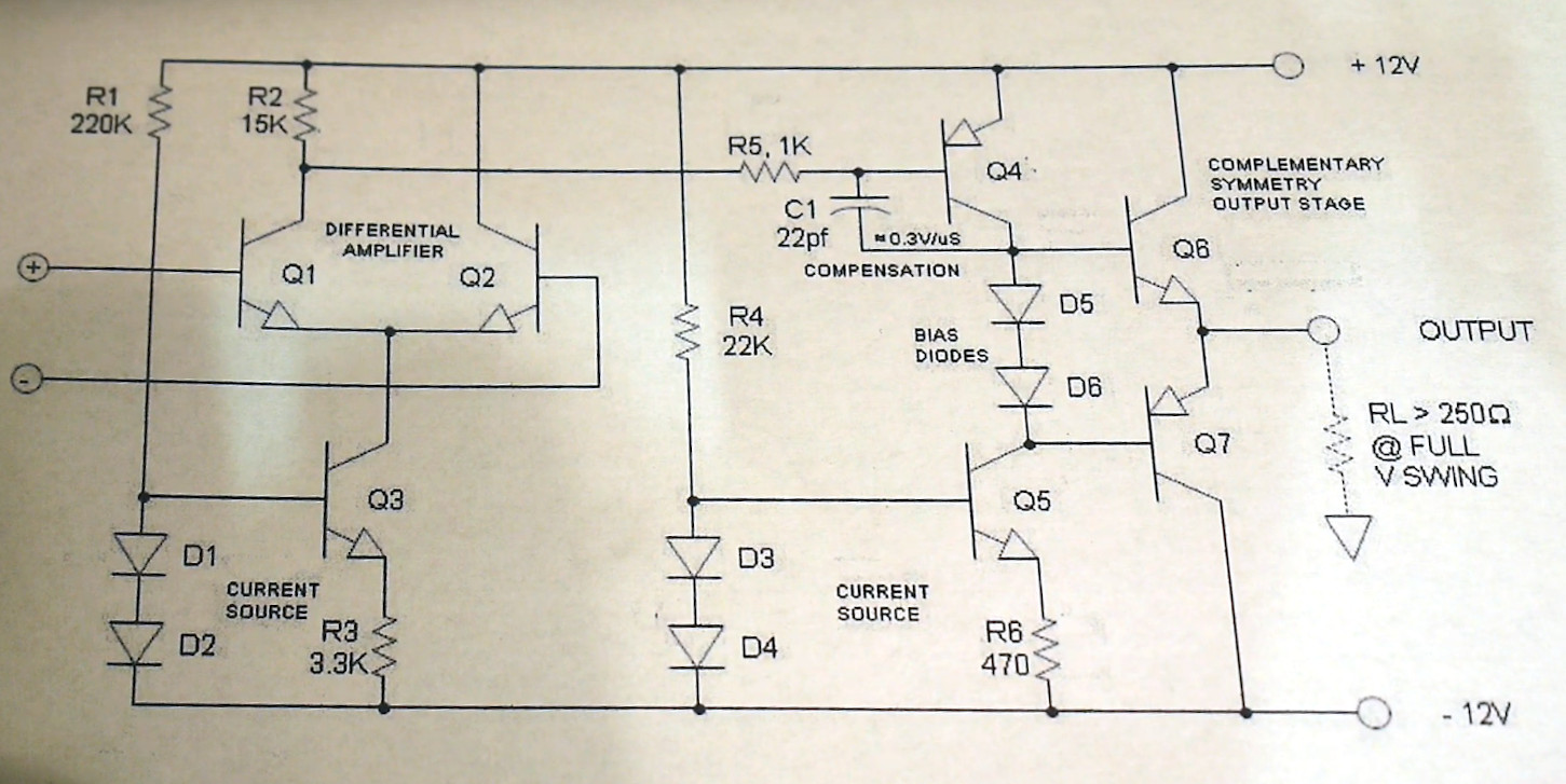
Op Amp Contest: Magnetic Core Memory The Dr Cockroach Way

No matter how memory technology marches on, magnetic core memory is still cool. Radiation-hard, nonvolatile, and so pretty. What’s there not to love? [Mark Nesselhaus] is no stranger to fun in-your-face electronics builds — judging from his hackaday.io projects — and this entry to the Hackaday Op-Amp contest is no outlier. This is a sixteen-bit magnetic core RAM demonstrator built upon glass using copper tape and solder, which always looks great and is actually not all that hard to do yourself provided you grab a new scalpel blade from the pack before starting.

Transformer-coupled differential front-end amplifier driving an SR latch.

For the uninitiated, the crossed X and Y wires each host a hard magnetic toroid which can only be magnetised by a field beyond a certain threshold due to the shape of the B-H curve of ferrite materials. The idea is for a required threshold current, drive the selected X line and Y line each with a current half of this value, so that only the selected core bit ‘sees’ the full field value, and flips state. This means that only a single bit can be written for each core plane, so to form longer words these layers are stacked, producing some wonderful cubic structures. These magnetic circuits are responsible for putting a human on the moon.

Reading the bit state is basically the opposite. A third sense wire is passed sequentially through each bit in the array. By driving a current the opposite way through the selected core bit, if the core was previously magnetised then the sense wire will read a short pulse that can be amplified and registered. The eagle-eyed will realise that reading is a destructive process, so this needs to be followed up by a write-back process to refresh the bit, although the core state will persist without power, giving the memory nonvolatile behaviour.

[Mark] utilises a simple discrete transistor differential transformed-coupled front end which senses the tiny current pulse and passes it along to a Set-Reset latch for visualisation. This simple concept could easily be extended to make this a practical memory, but for now, addressing is courtesy of a pair of crocodile clips and a discrete write/read pulse switch. We will watch with interest how far this goes.

DIY core memory builds are not a regular occurrence around these parts, but we see them from time to time, like this polished 64-bit setup. Core arrays are not the only magnetic memory in town, we’ve also seen DIY core rope memories as well.

Continue reading “Op Amp Contest: Magnetic Core Memory The Dr Cockroach Way”

Circuit VR: Even More Op Amps

In the last Circuit VR we looked at some basic op amp circuits in a simulator, including the non-inverting amplifier. Sometimes you want an amplifier that inverts the signal. That is a 5V input results in a -5V output (or -10V if the amplifier has a gain of 2). This corresponds to a 180 degree phase shift which can be useful in amplifiers, filters, and other circuits. Let’s take a look at an example circuit simulated with falstad.

Remember the Rules

Last time I mentioned two made up rules that are good shortcuts for analyzing op amp circuits:

  1. The inputs of the op amp don’t connect to anything internally.
  2. The output mysteriously will do what it can to make the inputs equal, as far as it is physically possible.

As a corollary to the second rule, you can easily analyze the circuit shown here by thinking of the negative (inverting) terminal as a virtual ground. It isn’t connected to ground, yet in a properly configured op amp circuit it might as well be at ground potential. Why? Because the + terminal is grounded and rule #2 says the op amp will change conditions to make sure the two terminals are the same. Since it can’t influence the + terminal, it will drive the voltage through the resistor network to ensure the – terminal is at 0V.

Continue reading “Circuit VR: Even More Op Amps”

An Op-Amp From The Ground Up

We are all used to the op-amp, as a little black box from which we can derive an astonishingly useful range of circuit functions. But of course within it lurks a transistor circuit on a chip, and understanding the operation of that circuit can give us insights into the op-amp itself. It’s a subject [IMSAI Guy] has tackled during the lockdown, recording a set of videos explaining a simple discrete-component op-amp.

The op-amp circuit in question.

He starts with the current source, a simple circuit of two diodes, a resistor, and a transistor that sets the bias for the two-transistor differential amplifier. This is followed by a look at the output driver, and we would expect that shortly to come will be a video on the output itself. Start the series with the first episode, which we’ve placed below the break.

His style is laid-back, making it a restful watch as he builds each circuit on a breadboard and explains its operation with the aid of a multimeter. If this whets your appetite for more on simple op-amps, we looked at the first integrated circuit op-amp back in 2018.

Continue reading “An Op-Amp From The Ground Up”

Homemade Integrated Circuits Hack Chat

Join us on Wednesday, August 14th at noon Pacific for the Homemade Integrated Circuits Hack Chat with Sam Zeloof!

While most of us are content to buy the chips we need to build our projects, there’s a small group of hackers more interested in making the chips themselves. What it takes the big guys a billion-dollar fab to accomplish, these hobbyists are doing with second-hand equipment, chemicals found in roach killers and rust removers, and a lot of determination to do what no DIYer has done before.

Sam Zeloof is one of this dedicated band, and we’ve been following his progress for years. While he was still in high school, he turned the family garage into a physics lab and turned out his first simple diodes. Later came a MOSFET, and eventually the Z1, a dual-differential amp chip that is the first IC produced by a hobbyist using photolithography.

Sam just completed his first year at Carnegie-Mellon, and he’s agreed to take some precious summer vacation time to host the Hack Chat. Join us as we learn all about the Z1, find out what improvements he’s made to his process, and see what’s next for him both at college and in his own lab.

join-hack-chatOur Hack Chats are live community events in the Hackaday.io Hack Chat group messaging. This week we’ll be sitting down on Wednesday, August 14 at 12:00 PM Pacific time. If time zones have got you down, we have a handy time zone converter.

Click that speech bubble to the right, and you’ll be taken directly to the Hack Chat group on Hackaday.io. You don’t have to wait until Wednesday; join whenever you want and you can see what the community is talking about.

What’s The Difference? Ask An Op Amp

If you’ve ever wondered why an op amp has the little plus and minus symbols on it, its because at the heart of it, the device is a differential amplifier. The problem is that — ideally, at least — it has infinite gain so it works like a comparator and that’s not what you usually want. So we put resistors around the thing to constrain it and get useful amplification out of it. [Stephen Mendes] does the analysis for you about how the standard configuration for a differential amplifier works. He assumes you know the stock formulae for the inverting and non-inverting amplifier configurations and uses superposition.

[Stephen] mentions that’s the easiest way to do it and then goes on to do it sort of how we would do it as a check. We think that’s the easier method, but maybe its a matter of preference. Either way, you get the right answer.

Continue reading “What’s The Difference? Ask An Op Amp”

Smart Outlet Cover Offers Lessons On Going From Project To Product

Going from idea to one-off widget is one thing; engineering the widget into a marketable product is quite another. So sometimes it’s instructive to take an in-depth look at a project that was designed from the get-go to be a consumer product, like this power indicating wall outlet cover plate. The fact that it’s a pretty cool project helps too.

Although [Vitaliy] has been working on this project for a while, he only recently tipped us off to it, and we’re glad he did because there’s a lot to learn here. His goal was to build a replacement cover for a standard North American power outlet that indicates how much power is being used by whatever is plugged into it. He set constraints that included having everything fit into the familiar outlet cover form factor, as well as to not require any modification to the existing outlet or rewiring, so that a consumer can just remove the old cover and put on the new one. Given the extremely limited space inside an outlet cover, these were significant challenges, but [Vitaliy] found a way. Current is sensed with two inductors positioned to sense magnetic flux within the outlet, amplified by a differential amp, and power use is calculated by an ATmega328 for display on 10 LEDs. Power for the electronics is tapped right from the outlet wiring terminals by spring clips, and everything fits neatly inside the cover.

It’s a great design, but not without issues. We look forward to seeing [Vitaliy] tackle those problems and bring this to market. For more on what it takes to turn a project into a product, check out our own [Lewin Day]’s story of bringing a guitar effects pedal to market.

Continue reading “Smart Outlet Cover Offers Lessons On Going From Project To Product”

Deconstructing A Simple Op-Amp

Maybe you are familiar with the op-amp as an extremely versatile component, and you know how to quickly construct a huge variety of circuits with one. Maybe you even have a favorite op-amp or two for different applications, covering many possible niches. Standard circuits such as an inverting amplifier are your bread and butter, and the formula gain=-Rf/Ri is tattooed on your forearm.

But you can know how to use op-amps without really knowing how they work. Have you ever peered under the hood of an op-amp to find out what’s going on in there? Would you like to? Let’s take a simple device and examine it, piece by piece.

Continue reading “Deconstructing A Simple Op-Amp”