At DC and low frequency, we can pretend wires are perfect conductors. At radio frequencies, though, there are many effects that you need to take into account for wires and cables. One of these is characteristic impedance. If you have a marked cable, you can look it up on the Internet, of course. But what if you don’t know what kind of wire it is? With help from [The Offset Volt], you can measure it as he shows in the video below.
This is one of those things that used to take exotic test equipment like an LCR bridge, but these days meters that measure inductance and capacitance are commonplace. The trick is simple: measure the capacitance and then short one end of the cable and measure the inductance.
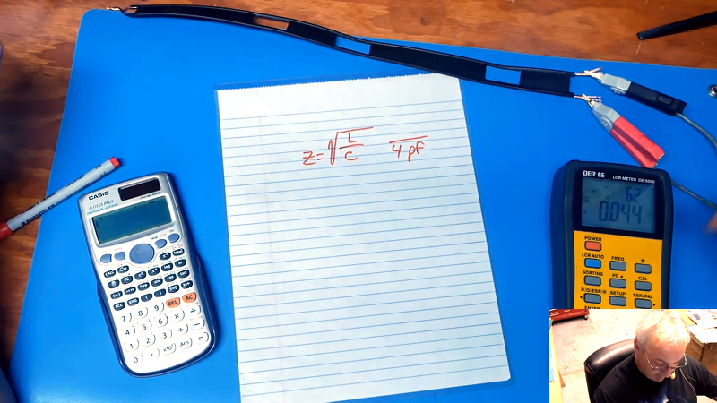
Once you have those numbers, it is easy to do a little math and determine the impedance. It doesn’t matter how long the cable is. The length will change the individual readings, but the ratio of the two readings will remain relatively constant.
If you don’t have a way to measure the inductance and capacitance, you can always build your own measuring gear. If you want to take a different approach, Tektronix showed us how to do this with a fast pulse back in the 1960s. But for that, you are going to need a scope.


I still don’t remember the visible differences between 50 and 75 ohm BNC connectors!
wait, I know this one.
One is rustier than the other..
boom! nailed it
For BNC connectors, the 50 Ohm version has plastic sleeve inside the ground leaves and has visible recessed plastic all the way to the center pin. The 75 Ohm version does not have the visible plastic insert. 50 and 75 Ohm versions can be safely physically interconnected.
http://www.cctvinstitute.com.br/bnc-75-or-50-ohms.html
shows some photos with the differences between the 2.
(why didn’t I try that first?)
You can use a TDR (fast pulse generator + a scope) to measure impedance of a cable and how uniform it is.
I also use it to find out where my cheap USB cable broke just the other day.
What’s out, there’s a Casio calculator in the video.
And a meter of some kind with yellow on it that isn’t a Fluke, sue fest ensuing tout suite.
Uh, edit: Watch out
and also RW edit “tout DE suite” :-)
Gracias amigo, mon francais est sehr schlect
*schlecht .. Mon deutcshe ist nicht muy bueno auch.
Ah, another “video”. Instead of a short text article or a link to a post with video option, everything is now being buried in videos. Nothing to print out. Audio probably isn’t adequate and a transcript won”t show things like the equation in proper mathematical notation.
It is not so much we are burning books, but not creating them in the first place.
+1
+1 Will wait for written article
Yes, I hate the trend to videos. Main reason is it takes too long to watch stupid video. I can scan the text much faster to find out if anything interesting is in there.
I can’t agree with you more on that. It seems everyone now-a-days want’s to be a video producer of one kind or another.
I saw a video a while back of some kid trying to show how he made his game controller faster. He kept bouncing around with “you do this then you do this and get some wire”. It was the most painful minute I ever spent on a YouTube video.
I get the most info just by scanning a document for a few seconds. If it’s something I want to know more about I actually go and read it..
I did a few videos on this too – here’s the most popular one:
https://www.youtube.com/watch?v=Il_eju4D_TM
hmmmm… only looking at the preview pic, showing a 2465, gives me thrills :-)
Oh it’s a 2465A.
I didn’t mean to offence you.
It’s such a Tektronix-fanboy thing to be so pedantic with suffix letters :-P
No matter how a transmission line is built, it only has a “characteristic impedance” (Z-nought) above some specific frequency (which is usually in the high tens or low hundreds of kHz and varies with the construction particulars). Below that frequency, the impedance is not constant, but is a function of frequency — as is the propagation velocity. And _that_ is the reason for all those Pupin coils being added to telco long lines prior to the advent of carrier telephony — on a long line, the voice highs got there ahead of the lows, rendering voice unintelligible. Adding inductance tended to equalize things. The frequencies used for carrier telephony were above that cutoff frequency, so propagation velocities were nearly constant.
I think you might have the wrong end of the stick here. The capacitance and inductance per unit length of the line will remain essentially constant, but the loss factors do change with frequency. Since the loss factors (series R of the conductors and shunt G of the dielectric) are a function of frequency and both will interact with the inductance and capacitance to cause a frequency dependent phase shift of the signal. This is what causes the group delay you are referring to or so I believe.
The reason for the apparent difference in impedance is the actual difference in measurement of the line at different frequencies due to the superimposed frequency dependent factors of series and shunt resistance which are part of the non simplified telegraphists equations.
Since the phase shift and the attenuation will be greater at higher frequencies it is the low frequencies that will arrive before the high frequencies. Using a higher frequency ‘carrier’ improves the situation because instead of the signal bandwidth being 300Hz to 4kHz it becomes x+300Hz to x+4kHz and if x were 100kHz then 100,300Hz to 104,000Hz represents a far smaller difference in the R and G parameters from the lowest to highest signal frequencies. To put it another way, 104kHz is less than 4% higher frequency than 100.3kHz whereas 4kHz is more than 1,200% higher frequency than 300Hz.
That’s as I understand these things anyway.
Can i use similar technique to verify antenna and matching network is 50 ohm?
Eg.: i have RF module which expects external 50ohm antenna and i want to check that my custom antenna circuit is up to the task…
Leaving open to read and watch into in more detail. Always can use some theory.