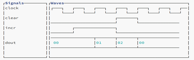
Testing software is — sometimes — easier than testing hardware. After all, you can always create test files and even fake user input before monitoring outputs using common tools. Hardware though, is a bit different. Sometimes it is hard to visualize exactly what’s happening. [Andrew Ray’s] answer? Produce simulated waveforms using ASCII text.
The process uses some custom tools written in OCaml, but the code is available for you on GitHub. The tool, called Hardcaml, allows you to write test benches for hardware — not a new idea for FPGA developers. The output, however, is an ASCII text waveform and common software development tools can check that waveform against the expected output.
You could do the same thing with a Verilog VCD file, of course, but it wouldn’t be as much fun to read. You’d want to use a waveform viewer to really see what’s going on. In fact, we wondered if it would be worth going the other way, to convert the Hardcaml output to VCD so tools you use to diff waveforms would possibly work.
We like ASCII art. In fact, we took our own crack at ASCII CAD back in 2002. You can even go 3D with your ASCII art if you like.


Um, actually…
Not ASCII. Probably ISO-8859-1.
shh all text generated by a computer is ASCII (even though the fundamental definition of ASCII has absolutely no relationship to text)
Latin-1 = ISO-8859-1 doesn’t have line drawing characters.
It’s unicode. For example, horizontal line is an em-dash. (0x2014)
Actually, the em-dash is just how it’s rendered in the html. The actual code uses unicode 2500 box drawing characters.
It’s like a scooby doo villain reveal in here.
Your ASCII CAD looks pretty cool, though, and it IS ASCII.
Would look better with a smaller line spacing. Would be perfect without those gaps between the output lines.
“The process uses some custom tools written in OCaml, but the code is available for you on GitHub. The tool, called Hardcaml, allows you to write test benches for hardware — not a new idea for FPGA developers”
Hardcaml is actually more than a testbench tool. It’s a complete framework for FPGA development, a bit like nMigen or Chisel, but in OCaml.
It’ll be a mess with proportional space fonts. That’s something won’t work too well as is when you want to copy/paste to on the web.
Some of the FPGA tools has a waveform editor for stimulus. Real life signals do not align exactly on clock edges.
Would be cool if you could define tolerances and perfect alignment means in tolerance.
You’d need to hit it with something more accurate of course but zoom could also be used to get a closer look.
I did this on a PC in 1991 for a timing system for an experiment. used / and \ for the up and down, so it really WAS ASCII.
no it wasnt, it was IBM cp437, and wouldnt look correct on any other non ibm pc clone
is there way to add such implementation to system verilog?