Surely the most straightforward way of creating a smart power strip would be to take an existing model and hack in some relays that you could fire with a WiFi-enabled microcontroller. But where’s the fun in that? Instead of repurposing a commercial power strip for his recent project, [Md Raz] decided to just build the whole thing himself.
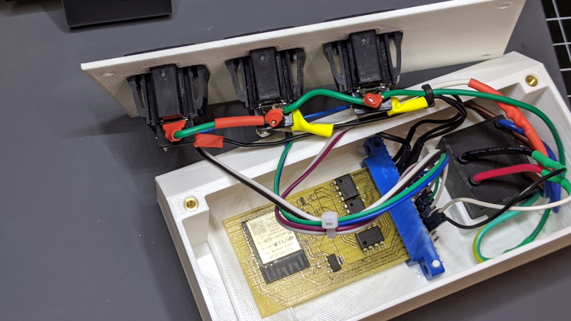
 The project started with a 3D printed enclosure that could hold the electronics and three panel mount sockets. The use of heat-set inserts makes it a bit more robust for future upgrade work, but otherwise it’s a fairly simple rectangular design. Nobody ever said a power strip had to be pretty, right? In addition to the panel mount sockets, there’s also a AC-DC converter to step mains voltage down to 5 VDC for the ESP32.
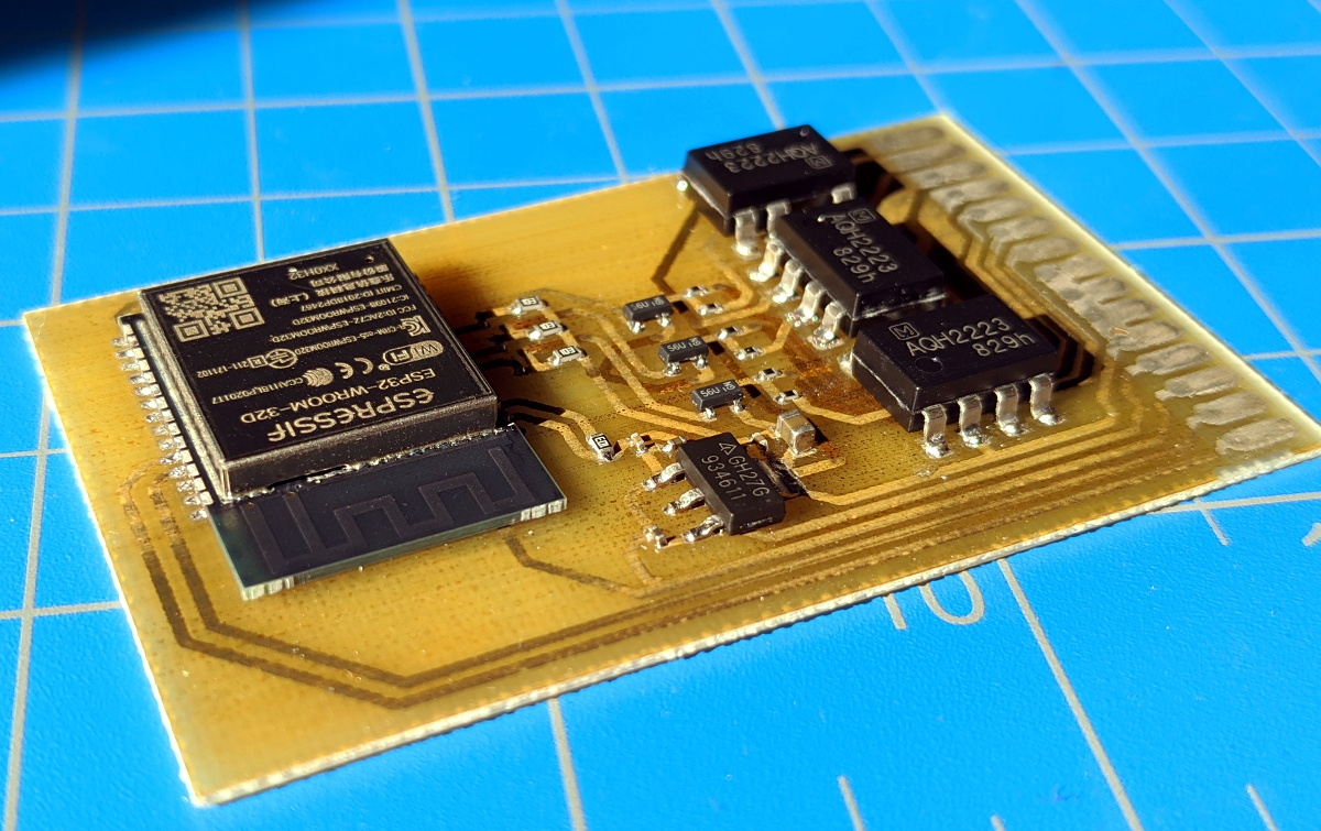
In addition to the microcontroller, the custom PCB in the power strip holds a trio of MOSFETs connected to AQH2223 solid state relay (SSR) chips. Once the ESP32 toggles the line attached to each MOSFET, the indicator LED above the outlet goes on and the appropriate SSR is thrown to turn on the power. With a simple web interface running on the microcontroller, all three outlets can be independently controlled from any device with a web browser.
If you’d like to limit your interaction with mains voltages, then we’ve seen some projects that commandeer the low-voltage side of a commercial smart power strip. But remember, putting a Raspberry Pi inside of a power strip might seem suspicious to some folks.


While I appreciate the use of optocoupled SSRs for mains protection, the lack of creepage distance and bare low voltage traces right next to mains makes them kind of pointless.
Yuk. nice home project, but…
– those outlets hanging half an inch over the ESP32 board without physical separation,
– the MOSFETs used instead of optocouplers (like who would trust an AQH223 SSR … copy?)
– the relative proximity of the WLAN antenna with the mains cable… antenna
– those legendary robust Dupont prototyping cables used
– time spend on designing and printing the box in … PLA
That would not stand an ordentliche Zulassung von TÜV where I live
isn’t PLA quite flammable?
PLA starts getting mushy at 60C and NEC temp limits for AC wiring insulation start at 60C and go up to 90C.
Not much overlap the PLA is outclassed.
Really the simplest way to control AC with a MC or small SBC is one of the zillions of home automation solutions. Get a Zooz 15 amp line cord thingie and a zwave usb stick for your raspi and go. I would think an air gap of 100 feet would be adequate for lightning protection LOL.
PLA is a great fuel. Once it softens at 60-100C it’s like Napalm and conforms and sticks to paper and wood. Once ignited it burns cleanly and leaves no ash, and the dripping liquid plastic carries the flame with it. I use my printer scraps as kindling in my wood stove.
I would have preferred regular relays for this project. These SSRs are fairly small, and have no heatsinking, so it will be very easy to overload when plugging in typical household appliances.
I will take great care then, never to use it for table lamps, electric razors or phone chargers, and only use it for reflow ovens, table saws and my welder. ;-)
Good thing there’s no fuse or circuit breaker in the thing, then.
I’m pretty sure the AQH2223s are the fuses. Although sockets would make them a lot easier to change when they blow.
Sockets are not required. They’re auto ejecting.
It’s got 3 sockets, so you can run your oven, table saw and welder all at the same time.
There needs to be some kind of Hippocratic Oath for people showing off stuff while shilling for companies like BotFactory. “Do No Harm” should apply.
I get that it benefits a company to show how to build something using their tools. But for a company shill to show people how to build something with incompetent engineering, with not even a nod to safety standards, is irresponsible. In the US, it could even be lawyer bait.
If you’re really wanting a solid, inexpensive (and safe!) network-controllable power switch, I can’t speak highly enough about digital-loggers.com aka webpowerswitch.com aka dlidirect.com Not a shill, just a happy customer who’s bought dozens of them over the last decade+.
Thanks for linking that site, i might look in to their PSUs. Better pricing than Tripplite too
+1…
Some of their products even seem to have an old variant of openwrt embedded…which has some interesting potential.
Also, good people. I’ve visited their shop a few times.
At the very least, a fuse/breaker where the line voltage comes is in order. Even then, there’s so many sketchy aspects of this design.
If you must display crappy projects (which respect to eletrical safety), at least inform about those issues in the article. Not everyone is aware of the standards (like EN60335, EN60950/62386 and IPC2221) for mixing high-voltage with low-voltage circuits (which Md Raz clearly is not).
Oh, they do warn in their instructable:
Ensure your components which will interact with Mains Power (the solid state relays, the connectors, and the plug receptacles) are rated for AC mains voltage and sufficient current (120V 60Hz in the United States, around 10-15 Amps).
Then they promptly go and use 0.9A-rated SSRs, and wire good for only 2-3 amps.
Then house it all in a plastic enclosure that turns into liquid fuel right before aforesaid wires burst into flame.
But that’s OK, they make a point of using thermally stable low temperature solder paste to secure the components to the PCB so, with any luck, the SSRs will fall off the board before the thing ignites.
Yeesh. So many kinds of stupid. And I mean that in the kindest possible way.
Thanks for pointing out the specifications.
That PCB layout is also pretty terrifying. There’s no markings to indicate where the parts handling mains power stop and the low voltage parts begin. Not that there’s a very large distance between the two. Or anything to protect the board if a stray drop of water condensed on it.
It’s double insulated by two layers of Hubris, one when it was thought it was okay to design like that, and secondly when it was decided to publish LOL
This is the winning comment right here 😂
Hubris might be insulation against critiques, but it won’t stop torts. Which is what might happen if some random kid decides to build this and burns their parents’ house down.
Adafruit is just a short E train ride away from the BotFactory. Maybe Lady Ada should pay them a visit and give them a lesson on responsible engineering on the web. Or just SLAPP them silly.
Oh.. same source as the (non)UVC light (non)sanitizer https://www.botfactory.co/blog/what-s-new-at-botfactory-1/post/designing-and-building-a-uv-sanitizer-120
Starting to see a trend there….
Aside from the electrical safety points which aren’t that well discussed…. Why oh why are they using an ESP32 to control four switches? I think you need another 4 cores for that to be reliable… Even an esp8266 if you have to….
Wow, you guys are brutal with your comments. While I understand what you’re saying your comments are just nasty. I agree that there are a ton of issues with this project, but the comments could have been made in a positive manner in the spirit of teaching rather than shaming.
Shame on you!
Agreed, some of the comments are the usual HaD fare: mean-spirited and unkind.
However, this device is promoted by a company, presented as an exemplar of design, and people are encouraged by the author to build it as designed.
As designed, this device is a hazard in several ways well known to any competent designer in the field. The engineering of it is negligent in the extreme. This might be rectified by some kind words of education, which would be appropriate if an individual were trying this out for themselves.
But when a company is promoting themselves by presenting this as a design for others to build, it’s far, far worse: it’s gross negligence, bordering on criminal, and genuinely deserves all the shame that can be heaped upon it.
Yes, the problem is that neither the original site nor the Hackaday article text present this as something along the lines of a homemade and potentially unsafe bodge. If it’s a “Check it out, I don’t really know that much about electronics, but I was still able to do something cool!”, that is something that should be held to a fairly loose standard.
The trouble is that BotFactory has presented this as something designed by a team of multiple engineers for others to copy. Given the slick page presenting it, the way they’re encouraging people to and the repeated references to the designers’ engineering backgrounds, this should be held to the same standards as a commercial product, or at least a commercial build-it-yourself kit. And the text of the Hackaday article didn’t really call out how unsafe this project is, leading to the commentariat to be a bit more vocal in pointing this out.
Thank you for the harsh but fair feedback. We neither intended for this to be used as an everyday item nor expected that people would use it as such. It was a project to show an alternative prototyping method that could be used as a learning exercise. We have updated our page to make it clear that this has not been designed or tested to comply with safety standards. This project was a proof-of-concept, a fun, side project to promote learning and experimentation within our team. Continuous learning, experimenting, and building from scratch are principles that defined us way before we formed BotFactory. We believe a company should be a vehicle to promote sharing and that through support and feedback everyone can progress. We will take note of the community’s response and act respectfully.
I would rather see this redesigned to eliminate the blatant dangers rather than a disclaimer:
Large air gaps between the low and high voltage areas of the PCB with appropriate markings so you can tell which sections are high voltage.
Uprated SSRs or MOFSETS with adequate heat sinking.
Overcurrent protection that trips before the SSRs.
Change the print material to something less flammable.
As it is, stuffing an ESP32 spaghetti-wired to a set of hockey-puck SSRs and stuffed in an off the shelf case would be a lot safer.
Quote: “comments could have been made in a positive manner in the spirit of teaching rather than shaming”
The spirit of teaching is difficult with this project.
As a person who has worked with HV / EHT I can tell you there is too much to type when you see a project like this.
Even air gaping is difficult to explain. Some will say you need X mm air gap but what does that mean when the conductivity of air is dependent on altitude (atmospheric pressure), temperature, humidity, contaminants, gas composition and other factors. And that is just one safety aspect.
It really should have some caution that working with mains voltages (or higher) should only be attempted by persons competent in doing so.
I used to tell noobs – you’re dealing with the danger of something that is invisible, can travel transparently through solid objects like metal or concrete, travels at close to 8 million km/h, can leap at you through the air and kill you in an instant.
While the comments here have a “brutal” tone, they are the actions of responsible people who are providing a caution that really should have been given with the original project.
HaD, Please stop posting stuff made by this BotFactory Inc. clown. In order to get any real information on the project you must surrender your Email address! This is the same guy who recently posted the very dodgy looking UV-C phone sanitizer. Now he brings us this outright DANGEROUS WiFi AC power strip.
wow. kamikaze mains AC handling. not often seen, but always heard. why on earth are there UL, TUV, CSA and all the other standards, anyway?
while i understand some commenters here complaining about the tone being “brutal”, let’s face it:
an outright dangerous contraption that puts your loved ones and your belongings at risk (and be it by sheer ingnorance) shall always be called out for what it is.
[Md Raz], do your homework and understand the possible dangers you impose on others before publishing this POS.
Honestly instead or paired with a web browser, I would use tasker and just make a few buttons on my phone’s home screen. I do this with my rpi and 433mhz relays and it works like a charm. It great when all you have to do is tap and icon your phone screen, you can even have it setup to change icons or color of icons based on rather the device is on or off.