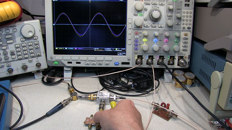
We live in a good time to be an electronics geek. It used to be only the richest or shrewdest among us had a really good oscilloscope, while these days it is entirely feasible to have a scope that would have cost a fortune a few decades ago, a logic analyzer, arbitrary waveform generator, and what would have once been a supercomputer and still not be in debt. One of the cooler pieces of gear for people working on RF electronics is a vector network analyzer (VNA) which used to be exotic, but now can be bought for very little. But what do you do with it? [W2AEW] has the answer.
We always look forward to a video from [W2AEW]. Even if we know about the subject he covers, we usually pick up something new or interesting. Like all of his videos, this one is intensely practical. Not a lot of drawing but plenty of scope shots and experimenting.
After all, you know that capacitors and inductors cause a different phase shift, but actually seeing it when switching out components live, is unforgettable. Besides, when he does do some “charts” we really like his pointer.
We looked at the NanoVNA which runs about $50. If you have money to burn, we liked the pricey Analog Discovery 2 which is not only a VNA, but a lot of other instruments, too.


If you are at all interested in RF I strongly urge getting a nanoVNA and making up a bunch of single sided PCBs with SMA connectors at either end. Then soldering leaded caps, coils and resistors to the center pin on the non-foil side and comparing the reflected and thru log magnitude and phase on the two channels.
You can see an initial example here:
https://groups.io/g/nanovna-users/topic/a_nanovna_amusement/74811973
It takes the witchcraft out of HF.
Have Fun!
Reg
Do the same with a TDR for the time domain version. TDR = Pulse generator + scope. Use a coax and no need to make PCB. Link below shows the reflected waveforms and a DIY pulse generator.
https://www.qsl.net/va3iul/Homebrew_RF_Circuit_Design_Ideas/TDR_Circuit_Signals_T.Engdahl.gif
@Reg says: “If you are at all interested in RF I strongly urge getting a nanoVNA and making up a bunch of single sided PCBs with SMA connectors at either end. Then soldering leaded caps, coils and resistors to the center pin on the non-foil side and comparing the reflected and thru log magnitude and phase on the two channels.”
Already done. This $23 USD ready-made PCB has 18 different circuits to be used when testing/calibrating a VNA, a NanoVNA in particular. The price includes two pre-made SMA(M)/MCX(M) coaxial cables and free CONUS shipping from California:
https://www.ebay.com/itm/50khz-1-5Ghz-NanoVNA-F-HF-VHF-UHF-VNA-Vector-Network-Analyzer-RF-Demo-Kit-USA/283878929656
The boards are sold on Amazon too:
https://www.amazon.com/Attenuator-Seesii-NanoVNA-F-NanoVNA-H-Analyzer/dp/B084MDG76T
Here’s a picture:
https://i.ebayimg.com/images/g/~IEAAOSwlTldqoGS/s-l1600.jpg
Here is the manufacturer’s Web page for the VNA Demo Board that explains what it is supposed to do and how to do it – in English with pictures:
http://www.sysjoint.com/en/content/?134.html
A VNA has been an indispensable tool for ham radio enthusiasts forever now. Get out in the real world and check out ARRL and the like.