When we draw schematics, we have the luxury of pretending that wire is free. There are only a few cases where you have to account for the electrical characteristics of wire: when the wire is very long or the frequency on the wire is relatively high.
This became apparent after the first transatlantic cable went into service for telegraph communications. Even though the wire was linear, there was still distortion on the line so severe that dots and dashes would overlap each other. The temporary solution was to limit speeds so slow that operators had trouble sending and receiving at those speeds. How slow? An average character took two minutes to send! That’s not a typo. Two minutes per character. By custom, Morse code assumes a word is five characters, so you could send a word every 10 minutes.
The first transatlantic cable went into service in 1858 and was virtually the moon landing of its day. Frustrated with how slow the communications were, an electrician by the name of Whitehouse decided to crank up the voltage to over 1,000 volts which caused the cable to fail after only three weeks in service. Whoops. Later analysis showed the cable was probably going to fail quickly anyway, but Whitehouse took the public blame.
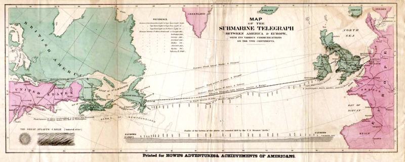
The wire back then wasn’t as good as what we have today, which led to some of the problems. The insulation was made from multiple coats of a natural latex, gutta percha, which is what dentists use to fill root canals. The jackets were made from tarred hemp and bound with iron wire. There was no way to build an underwater amplifier in 1858, so the cables were just tremendous wires laying on the ocean floor between Newfoundland and Ireland.
State-of-the-Art
While putting a cable under the ocean today isn’t a minor undertaking, it was even worse in 1858. Even the construction of the wire was a big deal. There were seven conductors and the iron wire used to armor the cable required two companies to make it. Famously, the companies wound the wire around in opposite directions leading to a well-publicized hack to allow splicing.
Laying the cable was also precarious. There had been some work laying shorter cables under small bodies of water, but nothing of this scale had been done before. There wasn’t a ship that could hold all 2,500 miles of cable, so they used two ships. After a few aborted attempts, the ships met in the middle of the Atlantic, spliced their cables and set off in opposite directions. The finished cable itself was nearly 2,000 miles long.
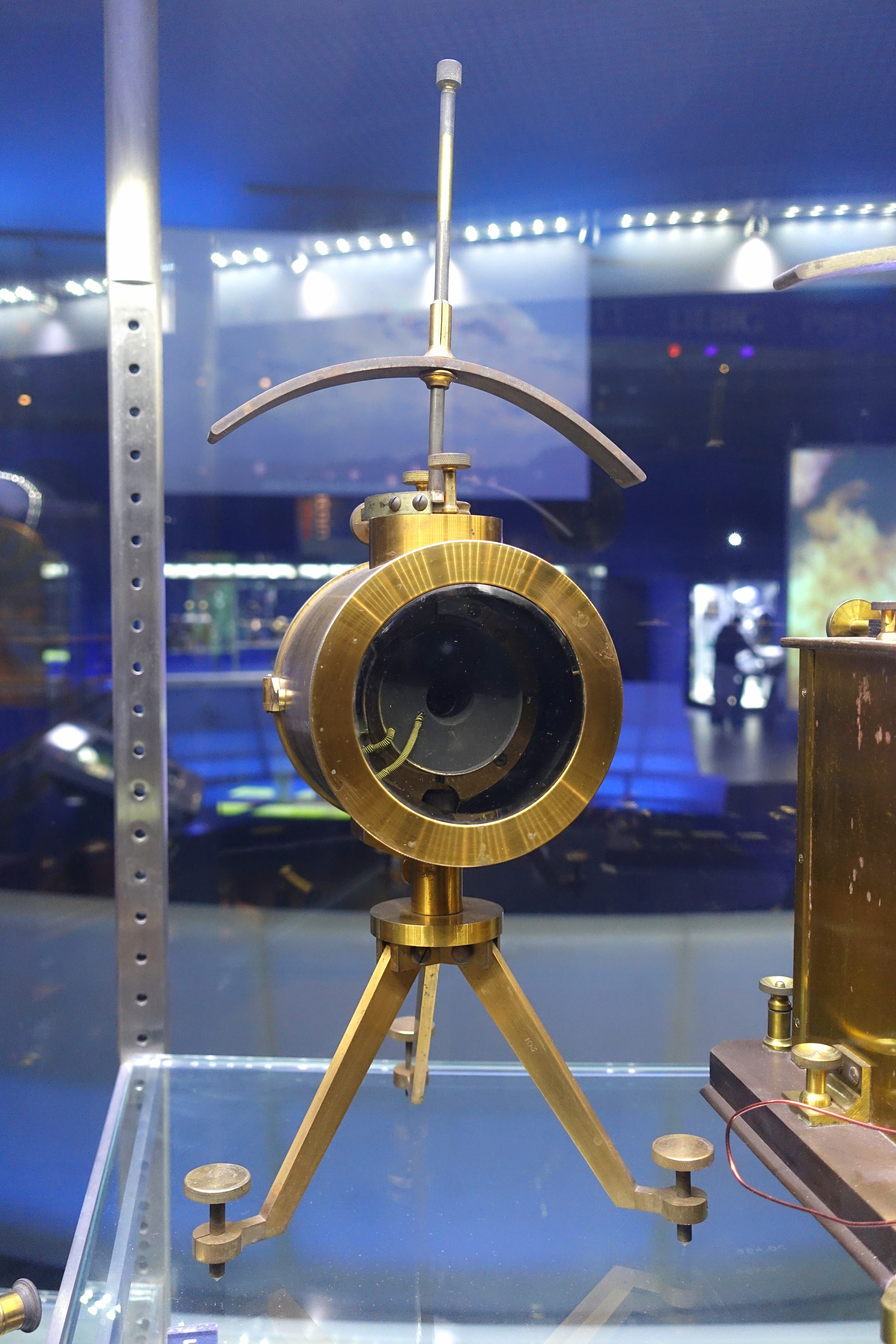
Even Morse code didn’t work the same on the long cable. Instead of on or off, the transatlantic cable used current flow in one direction to signify a dot and in the other to signify a dash — what we would now call a current loop. The receiver end was a very sensitive galvanometer that used a mirror to maximize sensitivity, developed by a man named Thomson who is better known as Lord Kelvin. Thomson and Whitehouse didn’t get along very well, but Thomson’s ideas and predictions turned out to be the right ones.
Degradation
At first, it was a mystery how the cable could distort the signal. Tests with underground lines by Whitehouse had been successful, although Thomson disagreed with those tests and feared the cable would only support slow speeds. The cables were long, but the speed of light is very fast. Even if the cable’s velocity factor had been 0.25, the transmission delay would only be about 44 milliseconds. Not enough to worry about. Plus, if it simply acted as a delay that wouldn’t change the communication speed, just the latency.
Thomson based his idea that there would be speed issues on the law of squares. This law says that a voltage step into a cable will have maximum current at a time proportional to the square of the distance down the line. It turns out this is not exactly correct because the formula didn’t take into account inductance and leakage, but it was close enough to show that there could be problems with the delay in the line. The cable project was well underway, but the new formula indicated that the cable should be larger to reduce resistance and decrease capacitance. But, as so often happens, no one wanted to hear that so it was disputed and ignored.
The Real Reason
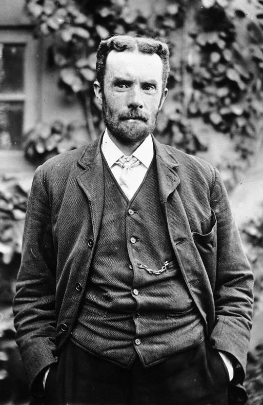 It would take Oliver Heaviside to get a better explanation of what was happening. Intuitively, you can consider that higher frequency components of a signal travel through the wire at different speeds than lower frequencies. A square wave, for example, can be thought of as a sine wave at the fundamental frequency plus the sum of all the odd harmonics. The higher harmonics travel faster than the lower frequencies, causing distortion. At some point, the higher frequencies of one part of the signal will catch up to the slower parts of the previous portion of the signal.
Heaviside formulated a pair of differential equations known as the telegrapher’s equations. In 1876 his paper provided a realistic model of a long transmission line and the work has applications in all sorts of transmission lines and even antennas. It turns out that Thomson’s law of squares was a special case of the telegrapher’s equations that ignored inductance and leakage.
The Solution
If you work through Heaviside’s math, you find out that distortion does not occur in a cable when for a given amount of cable, the ratio of leakage to capacitance is equal to the ratio of resistance to inductance. Mathematically if C is the capacitance per meter, L is the inductance per meter, R is the cable resistance per meter, and G is the shunt conductance (that is, the inverse of the resistance between conductors), you wind up with this formula, known as the Heaviside condition:

Usually, G is very small so G/C will be much less than R/L. So how can you balance the formula? Simply change one of the variables until the ratio works out. Decreasing R is attractive since lower R means less loss, too, but it also means bigger wire or more expensive materials, which is not always practical. Especially when you’re talking about a 2,000-mile cable. Decreasing capacitance has a similar problem. It does change the ratio, but requires more spacing or different insulation. You could increase G, but that will contribute to higher loss, so that’s not something you’d usually want to do.
That leaves the inductance, L. Some long cables have a built-in loading wire with high magnetic permeability to force the inductance higher. There is another way to deal with this and that’s through the use of discrete loading coils regularly spaced along the cable. This isn’t perfect, but it is practical and reduces distortion. These are sometimes called Pupin coils after inventor Michael Pupin. Pupin sued AT&T over a patent from George Campbell who used loading coils on telephone lines. Cambell’s patent was filed after Pupin’s, but the work appears to have been earlier. Heaviside’s work was even earlier, so Pupin probably didn’t have a good claim.
However, the value to AT&T was so large, they settled on buying an option for Pupin’s patent so they could control both patents. Pupin would up with about $455,000 over about 20 years — roughly worth $25 million today. But that was small change compared to AT&T’s savings. Lower distortion on phone lines meant they could use a cable to cover twice the distance they used before. There are estimates that AT&T saved $100 million in the first quarter of the 20 century. That makes the less than $500,000 Pupin got just a drop in the bucket.
How Times Have Changed
It’s hard for the modern mind to even imagine setting up a remote system when your only means of communication with the other side is a letter carried by ship. Bad weather could mean a transatlantic crossing would take weeks. The amount of money spent on the many cable attempts was also staggering. The successful cable took about $1 million. A huge sum in those days. After the first cable failed, some people claimed the whole thing was a hoax; truly the moon landing of its day.
Now, of course, wire is better and we don’t have to worry as much about the Heaviside Condition. In addition, you wouldn’t lay a 2,000 mile cable without repeaters. This not only combats loss but takes care of the distortion to some degree. But make no mistake. There are still plenty of undersea cables and they carry a huge amount of data.
While the history of technology like this is enjoyable in its own right, you have to consider what lessons you can draw from this story. First, wire is not perfect and behaves in unexpected strange ways that rarely make a difference (until they do). Second, ignoring technical advice for business reasons is often fraught with peril. It would be interesting to do a study on how much money was wasted because no one liked Thomson’s results that the cable would be “slow.” Granted, if the cable had failed anyway, it wouldn’t have been a huge loss, but still, having a cable with less distortion might have prevented the cable from failing as early as it did.
Pupin coils are largely a thing of the past. But the story of how they came and went can teach us things today. If you want to know more about the history of the transatlantic cables in more detail and how they evolved, we talked about that before. You might also enjoy the video below.


i felt so smart when i used V=IR and T=RC to get appropriate timing for “dallas 1-wire” on 30-foot runs. good to be reminded that was child’s play.
This was a very interesting article. But I wonder about one thing: Had they never before seen this distortion in long land lines? Less pronounced of course over shorter cables, but the effect should still be there…
Since they tended to use overhead single conductor wires, the capacitance would’ve been a lot lower than the coax form used underwater?
Those original telegraph cables were not coaxial; just a single insulated wire.
They were coax, the outside was wrapped in steel wire. Read the story.
This sounds resonable. They probably didn’t see this effect before in land lines because of using a single conductor. But, couldn’t that be done with underwater cables too? Or would there be a troublesome potential difference between ground on the european and american side? Or something else?
The answer is in the article: “The cable project was well underway, but the new formula indicated that the cable should be larger to reduce resistance and decrease capacitance. But, as so often happens, no one wanted to hear that so it was disputed and ignored.”
The cable key on the seabed so the capacitance was much greater than land lines. Also kind lines were broken up with repeated etc. I was born in a cable house on Valentia. My great grandfather move there to work in the station and my grandfather and father worked there till station closed in 1966.
Heaviside theory is well used also in power transmission lines. That’s where the surge impedance load of a power line comes from. Basically the power lines are kinda impedence matched to their loads. Like in the underground cable, the best way to match a line to its load is to play with the L of the line, by changing the number of conductors in parallel (1 to 4 usually) and the voltage level.
In case you were wondering, yes the Thomson in this story is the famous physicist who the SI unit of temperature was named after.
They had a bit of the original cable (maybe not actually used, I’m not sure) on view in the city museum in Birmingham, UK, when it was open pre-corono. With the various layers exposed it looked remarkably similar to modern steel armoured cable. Presumably it was there because it was made in Birmingham.
Equally fascinating is the story of the ship that participated in the laying of the first transatlantic cable: [SS Great Eastern](https://en.wikipedia.org/wiki/SS_Great_Eastern). It too was a marvel of engineering that only met its best use late in its life to lay the cable.
One correction, it is Mihajlo Pupin. But often Americans translate name to Michael which is easier to pronounce in US.
He was so proud of his Serbian origin that he added Idvorski (because he was from village Idvor, meaning “of Idvor”).
Do they have to take account of the mid-atlantic ridge / sea floor spreading? Or do they just lay a bit extra, loosely, to compensate?
The spreading of the seafloor is only a few cm a year, so laying it a bit more loosely should do fine.
Though, the actual separation area itself isn’t a sharply defined line, but rather happens a little here and there over a many mile wide area.
Though, over time it would indeed become a problem.
But, the whole idea of seafloor spreading weren’t even validated until late 1950’s…
About 100 years after the cable were put in place. (So they likely didn’t even know it were a thing to consider.)
And the ideas of seafloor spreading and continental drift weren’t even around in scientific circles before 1910.
(And engineering is basing things on scientific knowledge or empirically gathered experience. And since this were the first cable of its kind, there weren’t any prior experience and back in 1850’s science hadn’t even checked that yet.)
Though, most cables put onto the sea floor aren’t put under tension, and slack would be provided for the reasons that in case the cable breaks, one could lift it up with an anchor or the like and repair the damage. (Maintenance is kinda a required thing on crazily expensive investments.) So due to that it would likely have sufficient slack to survive a few decades worth of seafloor spreading.
And modern submarine cables have ample slack for similar reasons. (Some damage can’t easily be repaired under water. So easier to just lift the cable up and fix it on a ship.)
And only reasons why I know this were due to studying the various problems of undersea cables when trying to make a cost approximation for an HVDC cable between Iceland (a geothermal active place just outside the arctic circle perfect for renewable energy production) and Scotland (a place connected to the rest of the UK and thereby also Europe, a place in need of renewable power). Though, the cable would need to be mighty thick to not restively burn off a few % of the power one sends over… Apparently, Iceland and Scotland are far from each other… But for between 2-5 billion euros, it should be possible to send about 500 MW over that link. (And yes, 0.5 GW is a fairly pathetic amount of power compared to what the EU currently produces… (Though, technically one could build a liquid nitrogen cooled super conductive undersea cable able to send over many times more power with minimal losses. But providing vents for the resultant N2 gas will be a nightmare in itself… (Not to mention the power requirements for making LN2 to start with.)))
Sounds easier just to drill for geothermal in Scotland, I know Edinburgh rock is a very dead volcano, but you’d think if they went a way down into that old subduction zone there would be some heat down there.
Ah, nah, that’s super long dead, for some reason I was thinking it was only near a million. Was also thinking that there was a mildly active fault with a warm spring somewhere up there but must have been confusing it with some other Scotland.
Yes, the Scottish volcanoes were part of the “Scandinavian” mountain range that used to continue down into Newfoundland. Yes, Newfoundland is over in Canada, but stuff formed some 400+ million years ago happened when Pangaea were a thing.
Then that super continent decided to break apart (a rather recent event as far as the mountain range is concerned), ripping that mountain range into a couple of pieces creating some tid bits along the way, like Svalbard, part of eastern Greenland, Scotland and Newfoundland.
And the rather huge crack going through Scotland (where Loch ness is.) actually continues over in Newfoundland.
There were though likely volcanic activity in the region in more recent history, breaking apart mountain ranges is rather obviously a lot of geological activity, so that a bit of the mantel decides to leak out isn’t really unlogical.
Iceland on the other hand sits straight on top of the fault line, and will likely do that for the foreseeable future. (Foreseeable on a geological time scale that is. Unlike the Hawaii island chain for an example that will form a few new islands in that time…)
Though, progress in geothermal energy production is happening in Europe, France for an example has a fair few deep geothermal wells. (So going over to Iceland is a bit silly if one can do it locally. Though, in Iceland one only needs to drill a couple of hundred meters at most.)
But even Europe has active volcanoes, so its not like there is a few geothermal hot spots one can utilize. For an example Bath in Britain, or the numerous volcanoes in Italy, Greece and Turkey. Though, Iceland has the advantage of its sub arctic climate, with its rather cold summers, so running condensers is going to be a bit easier.
Iceland’s main downside is that it is very far away from any other country…
“in case the cable breaks, one could lift it up with an anchor or the like and repair the damage.”
Uh, in what universe would you be able to even find the cable, then lift both ends to repair it?
This one. A second attempt to lay a cable failed when the cable broke, so a third cable was laid, then the second was grappled for and repaired in 1866 (according to Wikipedia).
An excellent book on the subject for the layman is Gillian Cookson’s ‘The Cable’.
As an avid watcher of ‘Mighty Ships’ I can tell you that is a well practised method for pulling up subsea cable from the sea floor. It’s not the ship’s anchor mind you, it’s a special one built for that purpose. All you need is the GPS plot for where the cable was laid, you sail off to one side of where you think it is, drop your ‘cable grabber’ then sail perpendicular to the direction of the cable, as you cross over the path your ‘grabber’ should come into contact with the cable. It can take a few attempts but it is the go to method as I understand.
Reading from the shore station would provide a rough idea of the location of the break since the cable is electrically conductive. And (prior to the two WW) not much else down there in most areas. Atlantis being in a different part of the sea.
This is a surprisingly regular thing.
You don’t want to know how many submarine cables breaks every year.
Due to all sorts of things, everything from sailors casually dropping their anchor onto them (rather rare), to fishing boats trawling straight through them… (very common) Not to mention that a lot of icebergs have a tendency to scrape well over a meter deep trenches into the seafloor.
That there is a fair few ships out in the oceans that does little more than to go around and repair submarine cables isn’t really a surprise. Apparently, its big business when the telecommunication companies wants their billion (or more) dollar investment to not be a severed link…
I actually own a piece of the undersea cable that ran from Rye, NH to Ireland. Was given to me as a gift by T Vaughn of Micro Communiations a firm located in NHmany years ago.
More interesting: If you make signals which are just exponentially-increasing pulses (which go back to zero when they reach some threshold, but look like exponential increases on their ‘positive’ or leading edges), and then use them return-to-zero (ie, make negative versions to send logic 0 bits, positive for logic 1, etc), then this kind of signal has the unique property that its frequency content turns out to be immune to the kind of distortion you get on a cable not tuned to the Heaviside condition.
Not being on the Heaviside condition gives the wire a phase distortion that unequally retards different components of the signal you are trying to send, bringing them out of alignment and ruining the edges and ‘flats’ you are looking for, if you’re expecting ordinary binary (non-return-to-zero) signals. Throw in reflections from impedance mismatch at the ends, and you soon have unrecognisable slush.
But a real-valued exponential pulse could be thought of as consisting of a sinusoid with an imaginary frequency value. It kind of exists at right angles to the usual things you think of as having frequency, but given it’s shape, it has just one (imaginary) frequency component. (leading to it actually being a real-valued exponent). This is just the opposite of how you get a sinusoid out of a complex exponential function if you give it any purely imaginary argument. In this case, the imaginary ‘frequency’ causes the argument to become real — ie, just a plain increasing / decreasing exponential function.
The important thing in the ‘uncontrolled impedance transmission line’ case is that whilst it can lose magnitude, and change attack/decay rate, it will still arrive as well-localised ‘pulses’ which are amenable to detection by a threshold-detector using automatic gain control. In essence it is a ‘constant imaginary frequency’ signal that is transmitted for some ‘period’ of time, starting at some time. And those times, being associated with that single ‘complex frequency’, keep their relationship relative to each other in time no matter what linear distortion the line can do.
This is because the only shape such an exponential pulse can possibly be changed into (by a line with only linear-time-independent system properties)… is the same exponential pulse shape, with some attenuation and delay.
It’s a single ‘frequency’ value, get it? Moving it around leaves it basically looking unchanged, especially if you use an automatic gain control circuit to re-amplify it. With an arbitrary choice of gain, every exponential function looks the same.
If all the pulses are transmitted with the same ‘shape’ — ie specific choice of exponent, and they do all just look the same, just happening at different times, then they must come out looking just as they go in.
Even better, if you encode your binary data so that you have as many 1’s as 0’s, (ie, ‘whitening’ the data code, say by using 8b/10b encoding) then you can even couple it via transformers without having to worry about core saturation in said transformers.
If you understand the math behind it, it makes sense that the exponential pulse shape is the only one that linear time independent systems can’t change the shape of, apart from attenuating and delaying.
Every so often someone re-‘discovers’ this. But yeah. Go look up Ethernet PHY’s.
Of course, you’ll probably still want to terminate your ‘transmission’ line properly, so you don’t have to deal with reflections…
And the need to do so was the other real piece of understanding those old ‘telegrapher’s equations’ unlocked (seems like a pretty big hole in the article, TBH).
We *are* talking about no less than the birth of the electronics / electrical **engineering** discipline here: When complex math suddenly found an application, so that to this day, what separates the ‘engineers’ from the mere ‘technicians’ is whether they understand that math, and can apply it to solve real problems. Like distortion on electrically-long transmission lines (or AC line reactance).
The criticality of impedance matching, the uses of 1/4 and 1/2 wavelength stubs / transformers.
It’s no mistake that we really had to understand this stuff *before* mastering ‘wireless’! An antenna is really just an impedance matching transformer between a transmission line and free space, after all!
Just keep this whole thing about the un-distort-ability of exponential-time-shaped pulses in your back pocket! Never know when it might be handy to be able to send data down wires without controlled impedance… And yes, you can buy chips to do it. Just make sure you use the ‘magnetics’ so you’re not accidentally transmitting irritating interference, please! (or — use controlled impedance wiring, and complementary-logic signals so your ‘cable’ total current is not a function of your data — that also works).
When I was much younger, I read an account of sabotage on one of the first undersea cables. Someone had stuck a needle into the cable (shorting it?) The problem was detected during the time the cable was being laid, so it was reeled back up (IIRC) and repaired.
The Antique Wireless Museum has posted a video titled “The Pulse of the World”, made by the MacKay System in the 1920s, that shows its trans-ocean cable system in amazing detail. Laying cable, testing cable, splicing cable, repairing cable it’s all there, including land line and central office operations.
https://youtu.be/IsdYmSBOP_0