A newly licensed amateur radio operator’s first foray into radios is likely to be a VHF or UHF radio with a manageable antenna designed for the high frequencies in these radio bands. But these radios aren’t meant for communicating more than a double-digit number of kilometers or miles. The radios meant for long-distance communication use antennas that are anything but manageable, as dipole antennas for the lowest commonly used frequencies can often be on the order of 50 meters in length. There are some tricks to getting antenna size down like folding the dipole in all manner of ways, but the real cheat code for reducing antenna size is to build a loading coil instead.
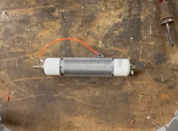
As [VA5MUD] demonstrates, a loading coil is simply an inductor that is placed somewhere along the length of the antenna which makes a shorter antenna behave as a longer antenna. In general, though, the inductor needs to be robust enough to handle the power outputs from the radio. There are plenty of commercial offerings but since an inductor is not much more than a coil of wire, it’s entirely within the realm of possibility to build them on your own. [VA5MUD]’s design uses a piece of PVC with some plastic spacers to wind some thick wire around, and then a customized end cap with screw terminals attached to affix the antenna and feedline to. Of course you’ll need to do a bit of math to figure out exactly how many turns of wire will be best for your specific situation, but beyond that it’s fairly straightforward.
It’s worth noting that the coil doesn’t have to be attached between the feedline and the antenna. It can be placed anywhere along the antenna, with the best performance typically being at the end of the antenna. Of course this is often impractical, so a center-loaded coil is generally used as a compromise. Coils like these are not too hard to wind by hand, but for smaller, lower-current projects it might be good to pick up a machine to help wind the coils instead.
Continue reading “DIY Loading Coil Shortens Antenna Lengths”


