Reverse engineering or modifying a device often requires you to access the firmware stored on a microcontroller. Since companies are usually not fond of people who try to peek into their proprietary data, most commercial devices are readout protected. [rumpeltux] ran into this problem when he tried to dump the firmware on an HC-12 wireless serial communication module for yet undisclosed reasons. Hacking into the device was a challenge that he gladly accepted and in the end, he succeeded by building a low-cost setup for voltage glitching.
Voltage glitching is a form of fault injection that has, e.g., been successfully used to hack the Playstation Vita. It involves the injection of voltage spikes on the power line in order to force the bootloader to skip security checks. The hard thing is trying to find the right shape of the waveform and the best way to inject the signal.
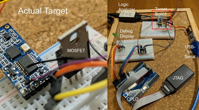
While there are already open-source boards for fault injection like ChipWhisperer, [rumpeltux] chose to build his own setup around an FPGA. By using a cheap EPM240 board, some MOSFET, and a USB-to-Serial converter, the total costs of the glitching setup were under 20 Euros. [rumpeltux] then recorded a larger number of voltage traces on the VCC pin around the reset phase and analyzed the differences. This helped him to pinpoint the best time for injecting the signal and refine the search space. After some unsuccessful attempts to glitch the VCC and GND pins, he got lucky when using one of the voltage regulator pins instead.
Be sure not to miss Samy Kamkar’s talk at Supercon 2019 if you want to know more about hardware attacks or how to eavesdrop on people using a bag of potato chips.


EPM240 is a CPLD, although Max II due incorporate some architectural features more common on FPGAs.
I do this at work, not for trying to hack firmware, but for testing new silicon for faults in startup. This is a more expensive way to do this but it works quite well: older/nicer HP/Agilent/Keysight power supplies have a jumper or dipswitch setting that makes them act as power amplifiers or voltage followers or whatever you want to call it, so they’ll dump out a substantial output when fed with an arbitrary waveform generator. You can use a microcontroller as your AWG, if you want. Some of the Agilent supplies could manage 5V/nS slopes, and I’ve bought some working 600W supplies, like the HP 6038A, for under $100 off ebay. It’s easier to set up the AWG if you have a GPIB or ethernet setup because then you can upload waveforms you’ve built in Excel to the AWG, but if you’re using a microcontroller with a fast DAC, like the more recent Teensys, that’d be a much easier interface for most home users. You don’t have to talk to the PS at all. It just follows. We use this for ISO 16750 startup testing where you’re simulating the varying voltage from a car battery as the engine is starting, and it’s worked really well.
You can also do this more cheaply but with more design work using, for instance, an OPA541 op amp as the voltage follower. We’ve paralleled a whole bunch of them to make a substantial fast variable power supply for an ISO 16750 test that needed 30A, while still managing 10V/uS rise times. It was nowhere near as robust as the commercial power supply, though.
Just got me wondering about the rise time of a typical ATX PSU if you bang the power good line up and down.
So go measure it then, like a real engineer
“I think I have a wire somewhere. One day I’ll have to go look for it.”
The power good line is an output from the equivalent of power supply supervisors in the PSU. It is not the power on/off pin which is you want to glitch. I don’t think the PSU would be too happy to see a glitch on the On/Off line nor can it switch fast enough in microseconds for a tiny amount of load.
It is probably easier just to take a modern day adjustable LDO with an /EN (enable) pin that you can turn it on/off at logic level. You can also fool around with adjusting the output voltage a bit just above the threshold.
All this makes me wonder why the brownout detector inside microcontrollers don’t catch it.
In this project, he’s glitching the internal LDO. Perhaps the brownout detector is measuring the signal before the LDO.
My question is also towards the parts that doesn’t have their internal regulator (for core) broken out. If only the vendors also monitor the internal rail for brownout properly (at least until exiting hidden system boot up code), they could close a security hole.
“Some of the Agilent supplies could manage 5V/nS”
— I can not believe that.
On looking, I think you’re right: that’s the slew rate of one of the AWGs I use. It looks like 5V/uS is more typical for the Agilent I use the most.
Sounds like you have a good environment for a hobby.
Aaaaand that was a reply to smellsofbikes. Goddamnit
No way! I was doing a very similar hack with similar hardware and got practically identical results. It’s like science or something.
I had got to the stage where the glitch on vcc didn’t work, but I was looking at that vcap pin with beady eyes.
Really enjoyed a link from the [rumpeltux] blog on this exploit. The link goes to a 35C3 talk on voltage glitching a Sony Vita device. Very informative talk. And the “random picture from Amazon” joke at about min 47 was hilarious!
https://media.ccc.de/v/35c3-9364-viva_la_vita_vida#t=1633
Does the Brown Out Detector fuse (like the one on the PIC microcontrollers) prevent the glitch technique to work?
No, the idea is to cause a dip in the voltage quick enough to make a single ROM read fail, but not enough to trigger BOR or any other process
Thanks, I had a project where the flash got corrupted because of a dodgy power supply and the BOD saved the day. If you can bypass it with very short pulses, it’s quite difficul to make a reliable product (on the other end, it is the developer’s responsability to make a sufficiently good power supply…)