We don’t know if aerodynamics is really a subject for dummies, per se, but if you are interested in flying or building drones and model aircraft, [Jenny Ma’s] new video that you can see below will help you get an easy introduction to some key concepts. (Embedded below.)
The show starts with coverage of lift, thrust, and drag, but moves on to topics such as stalling and coffin corners. If you have a pilot ticket, you might not learn a lot of new things, but for the rest of us, there are some interesting nuggets that you might not have known or might have forgotten from your physics classes in high school.
Actually, some of us are old enough that we learned an incorrect theory of how wings generate lift in school, and [Jenny] covers that and explains how we now know that the cause and effect of that theory were backward.
Speaking of bad theories, the video covers subsonic flight, although there is a little discussion of supersonic flight. Remember that before the X1 broke the sound barrier in 1947, many people thought it was not possible to do that.
This video won’t prepare you for designing the next jumbo jet or X1, but it might just help you next time you want to build a novel quadcopter or even a paper airplane.


So according to her, a cambered wing with an airfoil cross section will not generate lift at zero angle of attack.
yes, since the title says “aerodynamics for dummies”
This is correct. AoA is measured between the frontmost and rearmost points of the wing profile, so a zero AoA might look like it’s pointing “down”.
Camber is perpendicular to the direction of movement and not relevant.
If camber is not relevant, why have it? Camber increases lift of a wing for the same angle of attack. – thats why there are lift flaps on the backs of wings. A cambered wing will generate lift at zero angle of attack. So tthe shaoe of a wing can contribute to the amount of lift generated. Newtonian lift and the Bermnoulli effect both contribute to lift.
The video is incorrect in stating that the angle of attack is what makes the bernoulli principle work, and the reasoning as to why this must be the case (“airplanes can fly upside down”) is wrong.
Both effects generate lift. A wing with a flat bottom (zero AoA) and a curved top generates lift by the bernoulli principle, and a flat wing with a positive angle of attack will also generate lift by the newton principle. Most wings employ both effects, but only one is enough to fly. An airplane that flips upside down can fly by the reaction force principle.
The faster the plane goes, the stronger the bernoulli effect, and the angle of attack can be reduced to near zero. The slower you go, the more the wing is depending on the direct displacement of air, which is why airplanes use flaps at landing and takeoff.
What confuses the issue is the definition of ‘angle of attack’. The AoA of a wing is the angle between the direction of airflow before it hits the wing, and a line that passes through the leading edge and the trailing edge of the wing. A consequence of this definition is that when you lower the flaps on a wing, you are increasing the AoA, even though the direction the plane as a whole is going has not changed. So your statement, “camber increases lift of a wing for the same angle of attack” is not necessarily true, but only because of the definition of ‘angle of attack’. This is unfortunate, but the problem is, how else would you define AoA? This definition was chosen because it is easy and unambiguous to measure, but because of this, some apparently counterintuitive conclusions are sometimes reached.
BBJ’s right. I am not such a high level of genius and saw that before he said it. You guys can be way smarter than I and screw it up by fast/inattentive reading. Your haste is making waste.
I hope to learn something from the vid. The effects I read in the physics teacher’s personal aerodynamics book, as the only Jr in the slow boring class,(thanks mostly to Sr jocks ruining it,) never made sence, Bernoulli aside. Less pressure? Ok. But – over MORE area. Seemed like a wash to me… all props, aside.
I understand the less-pressure-but-more-area argument, but it misses something: the direction of the forces. You can think of a convex curved surface (the top of a wing) as three segments: the leading segment is tilted forward, the center section is (mostly) flat and horizontal, and the trailing section is tilted to the rear. The forces exerted on these areas are in all cases perpendicular to the surface – gas pressure is always a force perpendicular to a surface. So for the forward-tilting area, the force vector is also tilted forward, and for the rear-tilted surface, the force is also tilted toward the rear. Each of these forces has vertical and horizontal components, and the forward component of the forward section cancels out the rearward component of the rear section. When the NET force is calculated, these horizontal forces are removed, leaving only the vertical component, which is proportional to the area the wing would have if it was flat.
Something I see over and over, is the argument between Newton’s 3rd law vs. Bernoulli’s principle, when explaining lift. Anybody who makes these arguments is missing an important fact: Bernoulli’s principle is a DERIVATION of Newton’s laws!!! If something is happening due to the Bernoulli effect, it can be expressed using Newton’s laws.
But even then, it’s not the 3rd law, but the 2nd, f=ma, that best describes what happens. The “ma” portion of this, mass * acceleration, can also be thought of more usefully as the change in momentum. Conservation of momentum is probably the most fundamental physical principle, and in the case of the understanding of lift, we must consider how the momentum of the air changes as the air flows across both surfaces of a wing. I’m not great at explaining what happens over the whole length of the chord, but there is a simulator, Xfoil, that does the math, and XFLR5, which is a visual front end for Xfoil, that can be used to show where the changes in momentum, and therefore the forces, are distributed across an airfoil, and these are calculated solely using the velocity and change in velocity of the air at each point. There is no separate calculation used to consider Bernoulli’s principle, because Bernoulli’s principle is just a shortcut for explaining how this happens.
In fact, Newton’s three laws of motion are different expressions of the conservation of momentum. Nothing happens “because” of Newton’s laws. Physical objects move because of the conservation of momentum, and Newton’s three laws are descriptions of HOW they move.
1st law: a body moves at a constant velocity, unless acted upon by a force. That is, for any change in velocity (and therefore momentum) there must be a corresponding force. This force must come from somewhere, and we’ll see this in the 3rd law.
2nd law: the acceleration (change of velocity, which corresponds to a change in momentum for fixed-mass objects) of an object is equal to the applied force divided by the mass. Yes, I’ve changed f=ma to a=f/m; I hope you can see that this is the same thing. This is really just a quantification of the 1st law – it says how MUCH force it takes to change velocity (and momentum).
3rd law: For every force on an object, there is an equal force exerted in the opposite direction by that object. Now we’re looking at the other side – how the change in momentum is balanced. A force is exerted on an object, and because a change in momentum for that object cannot happen alone without affecting the total momentum in the whole system, there must be an equal change in momentum – and a corresponding force – in the opposite direction.
In the case of airfoil dynamics, the “object” is the wing, and the “other object” required by the 3rd law is the air. But the air isn’t a single object; it’s a great number of small objects, which without a computer are difficult to keep track of, which is why we have other observations, such as Bernoulli’s principle, to explain them.
Bernoulli’s principle is the EFFECT of air being forced to follow a path, with each molecule of that air adhering to Newton’s laws of motion.
You have as well some misconceptions right there.
AoA is defined as the angle between the incident airflow and the _chord_. Chord is defined as the straight line connecting leading edge and trailing edge (maximum distance between foremost and aftmost points). By definition, the chord is a straight line.
Camber is defined as the _deviation_ from the chord. It can be a complex function or in can be a spline or whatever other definition you want to give it.
Taking these two definitions, we see that increasing the camber is independent from the angle of attack. However, it does have an effect on lift, as it will increase the _circulation_ around an airfoil.
I also saw the video. It’s terrible from an aerodynamics perspective, and the girl really does not understand concepts like potential flow, Kutta condition or the most basic Bernoulli’s principle.
I’m not sure what the misconceptions were, on my part. I did not use the word “chord”, because it was unnecessary, and I did use the definition of chord in its place. As for camber, the example I was giving was just to show that the AoA of the wing can change just by extending the flaps, without making any other change to the airplane’s motion. What am I missing?
Camber is the distance between an airfoil’s chordline and centerline at a given x/c, guy, has nothing to do with movement lol
And at 10:26 she has the tail generating MORE LIFT than the wing. For civil aviation, the center of gravity of the aircraft is usually abour 20-25% of the mean aerodynamic chord length forward of the aerodymanic center which results in a dynamically stable design. The tail lift counteracts the moment created between these two forces and increasing or reducing that tail lift causes the aircraft to pitch up or down. For a typical aircraft, the tail never generates more lift than the wing in controlled flight.
I guess my professors at Purdue where I earned my Aeronautical and Astronautical Engineering Degree need to get in touch with Ms Ma and update all thier materials.
I wont even comment on the part about why planes cannot “simply fly into space”.
I’m OK with simplified explanations and overall revies of concepts, but not of people putting out wrong information.
Agreed, but I’ll go a step further. Einstein said something like, “Everything should be made as simple as possible, but no simpler.” The problem with “simplified” explanations is that they often go too simple, and just get it wrong, reinforcing what are sometimes intuitive, but just plain wrong, principles. She gets Bernoulli’s principle wrong twice in the video, as well. In the YouTube comments, the overwhelming consensus is that her explanations are great. Too bad they’re sometimes wrong.
The goal is not to be 100% right, but to not be wrong.
see: https://www.wired.com/2015/10/important-rule-science-writing/
If someone is going on Youtube as an ‘expert’ and professing to teach viewers something, they have the obligation to make sure they are correct and factual in what they say. Charisma does not equal correct.
I am not a pilot, this well made video taught me some new stuff.
Cute.
A “well made video” full of errors.
That will help you learn.
If you ever do ground school, you’ll be fighting an uphill battle against misconceptions.
>Remember that before the X1 broke the sound barrier in 1947, many people thought it was not possible to do that.
That’s not true. Many people KNEW it was possible to break the sound barrier – they knew bullets and rockets did it – what they thought was that it was impossible to fly an airplane past the sound barrier because every time they tried the airplane broke down or fell out of the sky.
Reason being that 1) propellers don’t work past the speed of sound, and 2) airfoils change their behavior and control surfaces stop working. They could get airplanes past the speed of sound in a dive, but they almost always crashed because of problem no. 2. They went into the dive and couldn’t get out – can’t pull up because the control surfaces fall behind the shade of the shock cone.
She got Bernoulli’s principle backward, saying at 3:47 that a fluid moving at a higher velocity experiences higher pressure. BZZT. She even shows in her diagram, higher pressure above the wing than below, which she contradicts in the next paragraph.
This was not just a matter of saying the words wrong – at 8:40, she makes the same mistake when talking about the exhaust from a jet engine.
Yeah. Should scrap it and repost after a fix. And lift doesn’t end in most stalls. The value just becomes too low. No proof-reading…
+1
Also, with respect to the “some of us are old enough that we learned an incorrect theory of how wings generate lift in school”, again, she’s wrong. And that whole flying inverted explanation… sigh… it is just so misleading…
There is something called the Kutta–Joukowski theorem, which basically states that the air flow cannot go around sharp edges – like the trailing edge of a wing – without going supersonic and involving spectacular displays of energy that simply are not there (imagine a bike making 90deg turns ‘Tron style’ and the instantaneous centripetal acceleration that you need in order to get that effect).
Thus, nature follows the simplest path, which is to force airflow to go around the airfoil in order to “leave” the sharp trailing edge at the trailing edge, without requiring sharp 180deg airflow turns.
When you plug this condition into the potential flow equations (much simpler than the Navier-Stokes, and producing very good results when compared with reality), the result is that you need to impart a rotational moment to the airflow, which is actually applied in reverse to the wing (and hence, you need will to counteract it with a stabilizer in order to fly straight). This rotational moment is just the right amount required to force the airflow to exit the trailing edge without any sharp turns. So, the airflow follows a “natural line” downstream after the trailing edge, instead of departing from mid section in the upper wing.
As a consequence, you get that the stagnation point, i.e. the point on the wing leading edge where the flow slows to a stop, will also move on the surface of the wing as a consequence of that rotational moment. Unlike what might seem intuitive, if the exit point needs to rotate clock-wise, the stagnation point will actually move counter-clock-wise. But that is the result that you get both experimentally and theoretically from the fluid models.
OK, now you have two points on the wing, the stagnation point and the sharp trailing edge, which define the upper wing travel and lower wing travel of the airflow. These two distinct paths DO obey the Bernoulli principle (for subsonic flight). The outside unperturbed airflow reaches the stagnation point, then travels around the physical barrier of the wing, finally leaving at the wing trailing edge. As you increase the AoA, the upper/lower wing travel ratio will increase, causing a pressure difference that imparts a lift force on the wing, and consequently also causes the airflow to be pushed downwards. Voilà, you’ve achieved flight.
The common misconception is that lift is generated by the lower wing, when actually the pressure drops more on the upper wing than it increases on the lower wing. Typically it is stated that the upper wing contributes for 2/3 of the Lift.
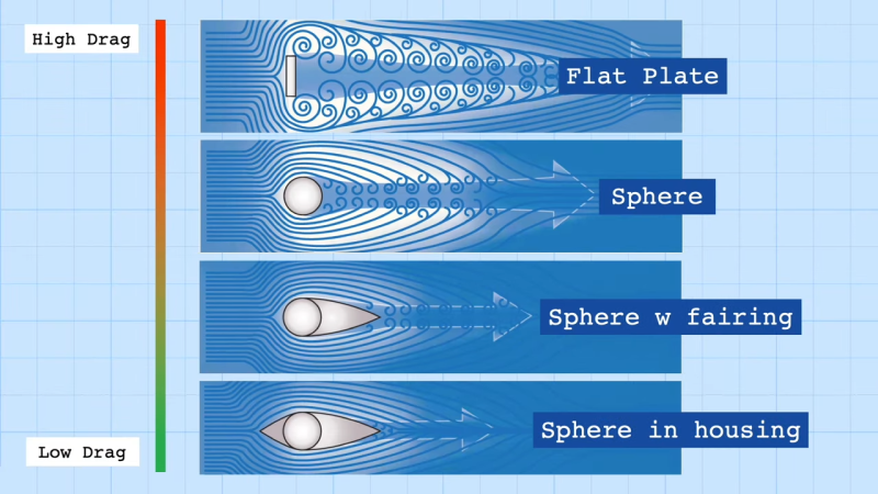
… The parasitic drag explanation is also wrong… she talks about it showing a small/big plane cross-section, when she should instead show a short vs long aircraft body…
Which may all be true, but this is the problem: people who want to know “how do wings make lift” don’t want to know to this depth. People want a simpler explanation, and there ARE simpler explanations that are “true to a point”. I think this is what [cliff claven] means by “The goal is not to be 100% right, but to not be wrong.”
For example, while the shape of the tail end of the fuselage affects parasitic drag more than the cross-sectional area does, with all else being equal, large cross-sectional area DOES produce more drag than small area, so while it may not be 100% right, it really isn’t wrong. Even the FAA tries to simplify things: there is an FAA circular (https://www.faa.gov/documentLibrary/media/Advisory_Circular/AC_103-7.pdf, see appendices,) that spells out how to make measurements on a Part 103 (ultralight) vehicle, and some of the measurements used to determine whether the vehicle meets the limit for maximum speed in level flight involve what position the pilot is in (sitting up or prone, e.g.,) whether it has wing struts, whether it has exposed landing wheels and whether they have fairings, and the engine power. All of this is insufficient to accurately calculate the parasitic drag, but when the worksheet is filled out, it gives you an indication of whether more accurate measurements are necessary. That is, if you pass based on the worksheet, the FAA won’t bother you with having to prove what your full power level flight maximum speed is. Not 100% right, but not really wrong.
>[Jenny] covers that and explains how we now know that the cause and effect of that theory were backward.
Except the explanation itself is wrong. It is simply wrong to say that the airflow striking the bottom of the airfoil is what causes the Bernoulli effect to happen.
First of all, the only thing that generates lift for the wing is the acceleration of a mass of air in the downwards direction, and this is because of Newton’s action and reaction, not to be confused with the Newton principle meaning the deflection of air by striking against the bottom of the airfoil. That’s where the explanation gets confused.
The same effect can be achieved in two ways: the Bernoulli principle which indeed works even when the angle of attack of the wing is zero and the bottom is level with the incoming airflow, AND the Newton principle which is when the incoming airflow hits the bottom of the wing and rebounds downwards.
The two situations have an identical effect: in the first case the curved profile of the top of the wing is speeding up the flow above and leaves behind a void the thickness of the airfoil profile, and in the second case the air striking the bottom of the wing is slowing down the flow below and also leaving behind a void equal to the area of the wing as seen from the front. Relatively speaking, these are the same exact thing: air flowing above the wing is made to fill a void behind the wing which requires it to move faster. Both cause the flow of air around the wing to accelerate downwards, which causes the reaction force according to Newton’s laws.
An airplane wing can freely switch between the two modes of operation or combine them at any ratio, so the same wing can fly upside down simply by having a greater angle of attack, and then flip back to right side up and use the Bernoulli principle. Airplanes generally use high angles of attack at lower speeds where the Bernoulli effect is less powerful, and switch to the the Bernoulli effect at higher speeds because having the wing flatter gives it less friction against the airflow.
And this is the third time I’ve tried to make this comment in different forms. HaD is still censoring me as a punishment for breaking rules they will not specify and crimes they won’t define. If I knew which opinion I’m not allowed to express, I could avoid it.
I haven’t watched the video, so please pardon my question if it’s answered in the video already. What I want to know is, if I were to attached a cargo box on top of my car, which end should point to the front for better fuel efficiency: the thin or thick end?
Can depend on the rest of the car, how long the roof is, and where on the length of the roof it is mounted. There’s even a possibility that it moves the center of least pressure of the system as a whole, such that it then behaves like a high angle of attack airfoil, in which case, although air might appear to streamline over the combo relatively smoothly, it’s actually incurring shape drag. This is because the “lift” is actually acting in a vector with a rearward component so is pulling backwards.
On older and less aerodynamic vehicles, there may be a bit of a “bow wave” off the top of the windshield, where air does not turn to follow the roof very well and leaves a turbulent lower pressure area. This will be within about 10 and 15 degrees of the front edge of the roof/top of windshield. If you can get the front of the cargo box nestled into that bow wave, then you may find it more efficient, than having it forward or rearward of that position. If in that situation the thin end fits into that wedge easier, then that may be more efficient.
Then there’s how the air comes off it. If you have a wagon, tall hatch or van, then possibly by aiming the air coming off the thin end to just miss the rear of the vehicle, you may find that it neutralises vacuum behind the vehicle somewhat, thus maybe even making it just as efficient with the box on as off. However, if you have a lower modern sedan or coupe body where the air is parted from the trunk at a certain point (Intended for clean separation and to raise the effective trailing edge of the “airfoil”) then aiming at the edge of the trunk may worsen economy. Therefore you’d want to have it far enough forward to aim at the top of the rear windshield, but this may not be possible. In this situation blunt end at the back might work better.
If you have tall roof bars, like it’s a whole 6 inches underneath it, and it’s nearly independent, then IMO it should be best blunt end forward, but mostly you’d have to ponder the effects on the aerodynamic system as a whole.
If however you’re also going to be pulling a caravan or travel trailer, you might want it thin end forward, as far back on the roof as possible, so it works as a “wind slammer” and breaks trail for the brick you’re pulling. Again, a system as a whole thing. Then again, you might not if it messes up your weight distribution, but you should have all the bulky light stuff in it, not your drinking water or canned food.
You know how you can quickly tell whether the video is any good? If it has the massive face of the creator in it, you know it’s just fluff.
This is unfair. The YouTube algorithm basically requires creators to do things like this (an explanation why is beyond the scope of a comment box). Many very talented presenters with quality content have very “YouTubey” looking thumbnails as a result.
Honestly it is a fair assessment, almost all channels which are chasing views with title slides like this are garbage, and you are better off sticking with the smaller channels which focus on quality content over focusing on extracting maximal revenue from youtube. The two aren’t mutually exclusive, but most people worth listening to run their channel out of passion.
Case in point, this video is absolute garbage, full of half truths and straight up factually wrong statements
Things I suppress when’the algorithm’ suggests me videos:
– big faces
– even bigger surprised faces
– arrows pointing at stuff
– bold text with no content, e.g. ‘this is incredible’ or ‘would not think this is possible’
– cleavage or other kind of sex-bait
The rule is simple: if more people start marking these videos down from “the algorithm”, they will have to change it. That also means not interacting with them (liking or unliking, commenting) and deleting them from the viewing history.
To be fair, she admitted that the information was partly incorrect, both in the description and in the comments. I applaud that.
Yes. She did that after I commented on the video.
Agreed.
There is so many wrong things in the videos:
– if lift is generated by the high and low pressure by compressed/depressed air, then the lift is more important at the rear of the wing. But most basic profiles have their lift maximized around 1/3rd from the front.
– Newton 3rd law will also create a strong pitch down momentum (increased by the 1st mistake above), needing to put the gravity center of plane to the rear of the wing, which is far from my rc planes experience tells me.
– Bernouilli principle is inverted. It serves her purpose so well that I wonder if it’s done on purpose…
– Based on this video, a flat-convex airfoil with no AoA (flat face parallel to airstream) will not creating lift. Which is wrong.
– Flying upside down is possible because of the camber of the bottom profile, which can create more lift that top profile when inverted if it’s AoA (negative in this case) is enough.
Experiences have shown that the up and down airflow have slight speed difference that matches enough to verify Bernouilli. The general actual consensus is that lift is created by Bernouilli for the most part and Newton 3rd law for a small part. There is no actual unified theory because.
Bernouilli “small stream-high speed-low pressure/large stream-low speed-high pressure” is right when you consider the whole airstream: the top stream is more restricted by the more cambered face than the bottom stream, thus speed difference, thus pressure difference.
Well, I wrote a long response to this, and it got posted in the wrong place – it’s up there under Rob’s comment, and starts with “I understand the less-pressure-but-more-area argument.” I won’t repeat it because it’s long, and it annoys me when I see posts repeated. It also addresses the “Bernoulli vs. Newton” argument, which wasn’t really a response to your points.
But to directly address some of your points:
1) Your first point: the forces imparted by the airflow are related to the rate at which the momentum of that air is being changed, and this is greatest over the parts of the airfoil with the greatest curvature – more curvature = direction changing fastest, and a change in direction is a change in momentum. Most of the force on the top of the wing is in the first 1/3 of the chord, because that’s where most of the curvature is.
2) “Flying upside down is possible because of the camber of the bottom profile”. This is not only wrong, but 180 degrees wrong, but I think you’re just using the word “camber” wrong. Camber is the ASYMMETRY between the two acting surfaces of an airfoil. Flying upside down is easiest when you have a symmetrical airfoil (zero camber), because then the lift-vs-AoA curve is exactly the same either direction. Flying upside-down is possible for the same reason that flying right-side-up is possible – because as you force air to change its direction (by giving it a surface to follow), there is a corresponding change in its momentum, and this imparts the old equal-and-opposite force thing, et voila, lift. All of the fancy curvature on wings is about keeping the airflow smooth over the wing, over the whole range of AoA you’re concerned with, because when airflow goes turbulent, it doesn’t stay stuck to the surface, and loses its “sucking power” on the top surface.
My comment also was misposted, not under Rob’s (I had to activate javascript and this probably messed the CMS).
My first point was to show the absurd of the “upper depression” use of the video, which would create the most lift by the end of the wing.
French speaker, so the “camber” was for me as the shape of the upper and lower profile (“cambrure”), not the actual “mean camber line” (simplified usually as “camber”, which represent the assymetry of profile), so “convexity/curvature” would have been better used maybe (or upper/lower camber).
Newton vs Bernouilli: My “There is no actual unified theory because” sentence is incomplete (probably due to the script activation). Here the whole sentence:
“There is no actual unified theory because both of the explanations relates to the same phenomenon but viewed in two different physics models.”
Both are true but both are a little too simplified (this is the principles of physic models) to accomodate every aspects of the whole thing.
I remember seeing one day the lift explanation using energy conservation (newton laws of movement relates also to the same aspect, using forces and movement instead of energies).
Didn’t watch the video. Read the book instead:
https://www.amazon.com/Stop-Abusing-Bernoulli-Airplanes-Really/dp/0964680629
Hokay, here’s my take on the bad explanation in the video and the top comment thread, which didn’t really slot in conveniently under another post in there, so here goes…
I think she’s conflating several ideas, vis a vis the Bernoulli lift and the flat plate lift at a positive angle of attack. I don’t know if this is because she doesn’t understand it, or is in fact just trying to dumb down the whole mess… So here is the thing…
Asymmetrical airfoils at zero incidence angle (zero angle of attack) generate Bernoulli lift off their upper surface well at certain scales and speeds. Fortunately those scales and speeds fit into a useful envelope under earth gravity at standard air pressures and moderate heights. This is the low subsonic realm, occupied by a large range of general aviation aircraft, or as heavy/fast commercial and military pilots like to refer to them, bug smashers. The immediately subsonic zone, often called transsonic, whether aircraft flying in it are capable of going supersonic or not has different effects begin to happen. Near the speed of sound, if you have air trying to go a lot faster over the top of the wing than the bottom, guess what happens, yeah, it’s trying to break the sound barrier there, leading to all sorts of weird crap, buffeting and loss of control, also large power requirements to compensate the compression drag. So at this point you do not want a lot of excess camber, you want a thinner wing, which at high speeds is making plenty of lift, in fact, if you make too much you’re fighting against it which makes for drag again. Also it was found you want to move the maximum depth and also the center of pressure back from about 30% chord to about 40% chord or more to delay shockwave formation. So now you’ve figured out how to travel fast, but when you gotta go slow again, guess what you need to stay in the air? Yup, more angle of attack because you can’t have a thicker wing.
Now if you have military plane, you want it to be agile, carve up the sky to attack enemies or avoid missiles, so you maybe want it to fly as good upside down as right way up. You’re likely to give that plane a symmetric profile airfoil, because a) much
camber lift makes it hard to screw around near the speed of sound or go past it, and b) you’ve gotta dial in angle of attack for low speed flight anyways, so what the heck does it matter to have it symmetrical and be 3% worse at low speeds than the asymmetrical but still thin one. Well the same sort of thing goes for slower planes designed to be good at aerobatics, it will have a symmetrical or semi-symmetrical profile, so that angle of attack does all the work.
So why don’t we skip all this crap and just use flat plates? Well at a smaller scale, i.e. models, that actually works pretty well and the observed differences between those and a “proper” section often fit within the error bars of how you are making that determination. However, models do not need such “man rated” safety characteristics as full size planes do, even if maybe some smaller ones could still get away with a flat plate. The airfoil shape delays stall, this is when the air separates from the top of the wing and it no longer generates lift, so an airfoil symmetric or not, can climb at a higher angle of attack and a lower speed than a flat plate airfoil before it suddenly falls out of the sky. Now this also means that a cambered airfoil lifts sooner than a flat plate, so will recover from a stall quicker. It will be noted then that aircraft like the Piper Cub known for having a flat bottom high cambered section have very docile stall characteristics. It will also be noted that if you happen to find video of anyone flying a (full size) Cub upside down on the original wing, it will need a lot of angle of attack (Making a lot of drag too) to stay in the air. (I’m not entirely sure the original motors are actually up to maintaining level flight like this) Then also there is less parasitic drag from a good airfoil than a flat plate making the same amount of lift, which is noticable for fullsize aircraft, so airfoils will be used for efficiency.
So in summary, airliners will have a relatively thin section for speed and efficiency just below the speed of sound and therefore will make most lift from angle of attack at lower speeds. Military planes, ditto, may have completely non-lifting section for high supersonic speeds. General aviation, sport planes with aerobatic pretensions will have symmetric sections and need angle of attack lift, sport planes that are tourers, or light transports at speeds below 400mph or so will want a lifting section, that is probably optimised for their intended cruise speed, neutral trim there, and will use some additional angle of attack methods at takeoff and lower speeds. Models, need not use a lifting section, unless ultimate efficiency is important, like competition slope or thermal soaring, and things behave a touch differently for them at their scale as they are working at lower Reynolds numbers. (It’s sort of like if you had to design a Jumbo to fly in treacle)
The stall speed of a 747 in treacle would probably be well under 1 km/hr. But then so would be the never-exceed speed!
https://www1.grc.nasa.gov/beginners-guide-to-aeronautics/learn-about-aerodynamics/