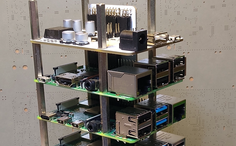
It isn’t that hard to assemble an array of Raspberry Pi boards and there are several reasons you might want to do so. The real trick is getting power to all of them and cooling all of them without having a mess of wires and keeping them all separated. The ClusterCTRL stack lets you stack up to five Raspberry Pi boards together. The PCB aligns vertically along the side of the stack of Pis with sockets for each pin header. Using a single 12 to 24V supply, it provides power for each board, a USB power connection, and provisions for two fans. There is also a USB port to control the fans and power.
There’s also a software component to deliver more granular control. Without using the software, the PI’s power on in one second and monitor a GPIO pin to control the fans. With the software, you can turn on or off individual nodes, gang the two fans to turn on together, and even add more stacks.
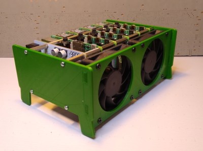 There is a case that you can print from STL files, although you can buy them preprinted on the Tindie listing where the bulk of information on ClusterCTRL is found. You could also have a 3D printing vendor run off a copy for you if you’d rather.
The power supply is a 10A 5.1V DC to DC converter. That works out to 2A per Pi and 51W total. The power supply for the input, then, needs to be enough to cover 51W, the power for the fans, and some overhead for regulator inefficiency and other small overhead.
We’ve seen a lot of Pi clusters over the years including one that is a good learning tool for cluster management. Of course, there’s always the Oracle cluster with 1,060 boards, which is going to take a bigger power supply.


cool build. looks like a good cooling solution. looks nice and solid.
Every damn Pi cluster article, like clockwork.
Maybe not [neimado], but always a reply with a permutation on ‘no substitute for a real cluster’, ‘can do it with Docker and a 555’, ‘slower than X’, ‘why not old PCs’.
Can we please get 1-click canned replies in the comments so these poor folks can avoid wasting valuable seconds on glib responses?
Ironic shitposting is still shitposting.
What’s wrong with LEGOs and skyscrapers? They have some exceptionally nice models!
Sadly … not real OpenHardware …..
Sorry .. but nope.
Yeah whine about stuff that doesn’t exist, really special of you.
If you don’t grow the silicon boules in your kitchen, is it really open hardware?
So buy some open hardware and do it yourself. The goal of the Pi was never about being open in the first place. It was designed to be as cheap as possible.
Do you click into Pi articles just to say that? Why are you bothering with the topic?
To the creators, trade out the LMZ23610 for a LMZ12010. It’s $5 cheaper and just as good if you don’t need adjustable switching freq.
I really like their idea of a power backplane via the GPIO header since we still don’t have a CM4. One thing that would make it even better would be a remote serial console to each of the Pis. It could be as simple as a 1:5 MUX and a single channel. They’ve got most of a cluster BMC there, and it would be icing on the cake to add a low-level early remote console to the mix.
I’ve not been able to find out, but is this a cluster as in 5 computers working as one? Or 5 seperate computers just in a convenient stack and psu?
As in the hardware, its five separate machines. The clustering comes from software.
What’s the biggest rack build to date
With ras pi 4, 8gb? Any one wanna help on this
Took me a few moments to work out how the Pi’s were linked together, but it actually looks like a clever way to stack them together, regardless of any other aspect of the project.
You can route power, buses, add switching and everything on the ‘backplane’ while still getting the compact vertical stacking that is desirable.
Nice.