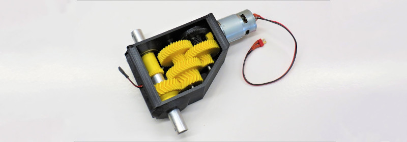
Typically, when we think of 3D printed parts, we think of unique parts with complex geometries that would be hard to fabricate with other techniques. Strength is rarely the first thing that comes to mind, due to the limitations of thermoplastics and the problem of delamination between layers. However, with smart design, it’s possible to print parts capable of great feats, just as [Brian]’s high-torque gearbox demonstrates.

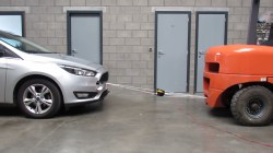
The gearbox consists of entirely 3D-printed gears, along with the enclosure, with the only metal parts being a few bearings and shafts. Capable of being produced out of PLA on a regular FDM printer, [Brian] has successfully tested the gearbox up to 132 kg∗cm. The suspicion is that there may be more left in it, but some slippage was noticed in the gear train when trying to tow a Ford Focus with the handbrake still on.
Even better, with the addition of a potentiometer, the gearbox can be used as an incredibly tough servo. [Brian] demonstrates this by lifting 22 kg at a distance of 6 cm from the center of the output shaft. The servo does it with ease, though eventually falls off the bench due to not being held down properly.
It’s a build that shows it’s possible to use 3D-printed parts to do some decently heavy work in the real world, as long as you design appropriately. [Brian] does a great job of explaining what’s involved, discussing gear profile selection and other design choices that affect the final performance. We’ve seen similar work from others before, too. Video after the break.


This and an actual servo would be great for the belted Z on one of my printers…
Someone has already done similar, and ran into banding issues that repeated every two millimeters. You’ll be better off with a Rino worm drive, can usually find them on ebay for around $100 or less.
https://drmrehorst.blogspot.com/2018/04/designing-low-cost-printable-worm-gear.html
Nicely done!
One recommendation – avoid flat head screws unless there’s a really good reason to use them. If they’re overtightened in plastic especially, they are effective wedges and will crush the outer shells and/or split the parts entirely. Better to use pins for locating parts and socket head cap screws (or similar) for fastening, with washers to distribute the force if possible.
you mean countersunk screws in a non-countersunk hole, right?
No, I’m sure he meant flat head screws (which is the formal name for the type of screw that sits flush with the surface in a countersunk hole) in any kind of hole (because even with a countersink, a tapered head will try to split the substrate).
You may be mistakenly thinking of slot-drive screws, since a lot of people call the associated screwdriver “flat”.
Those are most certainly countersunk screws, regardless of the type of drive. The type of screw you’re referring to is commonly called a ‘cheese head’ screw (because the head of the screw looks like a wheel of cheese).
Not to be confused with socket-head screws, which typically sit in recessed hole (counterbore).
I’m just sayin’ – McMaster disagrees with you: https://www.mcmaster.com/screws/flat-head-screws/
Think we have a US vs European difference in terminology here…
How doesn’t the potentiometer get turned to bits when using the servo as a winch?
Or does it have to be removed first?
If you look in the testing part of the video he removed the gear from the pot. He must just reinstall it for servo mode.