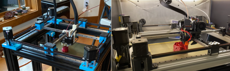
Simply having a few go-to 3D printer motion system designs is no reason to stop exploring them, as even small iterations on an existing architecture can yield some tremendous improvements. In the last few months, both [Annex_Engineering] and [wesc23] have been piloting a rail-derived crossed gantry architecture, a “CroXY” as it’s come to be known. Borrowing concepts from Ultimaker’s crossed gantry using rods, the Hypercube Overkill project, and perhaps even each other, the results are two compact machine frames capable of beautiful prints at extremely high speeds–upwards of 400 mm/sec in [Annex_Engineering’s] case!
Both gantry designs take a rotated MGN12 rail (a la the Railcore) and cross two of them, mounting the carriage at the intersection point much like an Ultimaker. Each crossed rail controls a degree of freedom with vanilla Cartesian kinematics, but each degree of freedom also has a redundant motor for added torque. Like the CoreXY design, this setup is tailored for clean prints at high speeds since the motion-related motors have been removed from the moving mass. However the overall belt length has been reduced tremendously, resulting in a much stiffer setup.
But the innovation doesn’t stop there. Both gantries also feature a unique take on a removable Z probe. When the machine needs to level the bed, it travels to a corner to “quickdraw” a magnetically attached limit switch from a holster. Once mounted, this probe becomes the lowest point on the carriage, allowing the carriage to travel around the bed probing points. When finished, the probe simply slots back into its holster, and the print can begin.
Both [wesc23’s] CroXY and a variant of [Annex_Engineering’s] K2 are up on Github complete with bills of materials if you’re curious to poke into the finer details. With commercial 3D printer manufacturers spending the last few years in a race to the bottom, it’s exciting to still see new design pattern contributions that push for quality and performance. For more design patterns contributions, have a look at [Mark Rehorst’s] Kinematically coupled bed design.


There’s a LOT of ghosting in that part. The rails have a lot of flex in the orientation that they’re used in. Simply turning them 90 degrees to a horizontal rather than vertical orientation would increase rigidity greatly and improve print quality.
The ghosting is a result of the rails osculating in the x-y plane as a result of the forces on them. Because there is no forced vertical osculation swapping the vertical and horizontal rigidity would reduce the oscillation that affects print quality.
That printer actually had a lot of cracked joints! The ghosting was likely because of that, if you checkout the annex engineering YouTube channel you can see some really high quality prints printed at 400mm/s. The rail rigidity certainly is a factor and we do have some plans to help it out!
Many people seem to not understand how 400 mm/s looks like. This video is not any close.
And in either case, what’s killing printing performance is acceleration, not top speed. Lower moving mass is a key here. Go Delta w/bowden feed for quick prints
We called this “ringing” instead of ghosting at Ultimaker. And, we wouldn’t have called this print “beautiful”, far from it. Balancing the mount of ghosting/ringing vs speed is something we where struggling with all the time. Sure, you can go crazy fast, at a high cost of quality.
And putting a heavy print head in there just makes it worse.
You can also see it’s not moving at 400mm/s, far from it. Acceleration/jerk settings are slowing it down a lot.
Now, the linear rails should solve one of the Ultimaker issues, which is X/Y/Z offset depending on the head position, due to the axes not being a 100% straight you get sinwave offsets in all directions. It’s small, but measurable.
Small gain, for a lot of increased cost (more motors, expensive rails)
But, it doesn’t solve one of the bigger drawbacks of the Ultimaker gantry setup. And that is the setup doesn’t scale, increasing the size causes all kinds of problems (including not enough stiffness, and making it stiffer increases the weight a lot more then other setups), scaling it down causes a different set of problems (including cost)
Thanks for the insight, scalability is definitely a huge issue. People have tried to use the same belts, motors, and rails from small printers on square meter gantries with predictable results. A lot of the fundamental physics behind these systems is kind of glossed over by hobbyist grade efforts. However, you do have to start somewhere and some of these projects lead to more polished versions in the future after the creators fill in some of their knowledge gaps. I’m sure the k2 printer could be improved to lose quality at a higher speed, there are probably some ratios between belt/rail rigidity and moving mass that could be optimized further (at an increased cost).
I’m interested to know why a sinewave offset would occur, do you have any resources on that? I would have expected a different error. Also, while ringing is basically a structural issue that needs to be solved physically in this case, known offsets could be calibrated out if sensing is relatively cheap. For example the droop due to gravity in large robotic arms is characterized and counteracted to achieve precision at larger scales.
All the issues that is visible in this video seems to have been 100% migrated, i can see that on the newest youtube video. 20k acel and no visible ringing.
“mitigated”?
The sine wave error on Ultimakers comes from the 8mm smooth rods that are used for linear guides AND belt transmission. For instance, if an 8mm rod is bent, as that rod spins to move the axis, the axis is forced up and down (and side to side, but that is much less visible) with the motion of the smooth rod. This motion starts off small from the furthest side from the bent 8mm rod, and increases in amplitude as the carriage approaches the side nearest the bent rod.
If you hit just the right (wrong) frequency, this can compound with the oscillations from the cantilevered Z and lead to catastrophic failure.
As a note, I believe this particular video was taken before Klipper had implemented input shaping, which can largely get rid of this type of ringing artifacts without harming print speeds (much). In the end, the part was very much usable, but yes it did have ringing. Newer versions have also tackled some other problem spots, like the moving mass of the carriage and improved part cooling. As mentioned elsewhere, there was other damage to the XY joints that contributed significantly to the ringing as well.
Cool! Thanks for the response
CroXY rails are now rotated so they are horizontal. I’m getting really good prints. I also experimented with sistering a 2020 on the top rail. I saw a barely perceptible decrease in ringing at 6000-8000 mm/s^2 with the 2020.
Thanks for responding, have you considered a less elastic belt? If a stiffer rail didn’t make a big difference then elasticity in the belts (or other parts of the frame) could be to blame.
Very cool project! You’ve achieved really good print quality at speed and seem to have good plans for going larger in the future.
CroXY supports 12mm 2GT though I have only ran it with 9mm. I’ll install 12mm next time i tear apart the XY system. Beyond that, there’s not a lot of options for belts. FHT makes a 1mm pitch with CF reinformcemnts (iirc), but not in long enough lengths. Proper GT3 would be an option.
I doubt turning the rials would help- the design is throwing around two heavy steel rails at print speed along with the extruder. It’s going to ring whichever way you orient the rails, especially with high acceleration and jerk.
While it wouldn’t help with the x/y elasticity caused by belt elasticity, it would reduce elasticity from the un-backed rail flex. if you need convincing look into the 2nd moment of area for a rectangle, the rails should be several times stiffer under bending in the direction that causes ringing if oriented differently. It would probably be smarter to just back them with extrusion, but reorienting them wouldn’t take any extra parts.
“forced vertical osculation”
Sounds like a middle management act you don’t want to have to resort to.
if you go to the annex discord you can see there is no ringing on normal prints. I ran 20k acceleration 400mm/s no ghosting or ringing, its also on the youtube channel :) and that is a 400×400. if you need scaling you need to look at K1 insted
Swear I hear sandstorm in there…
Although it would take up more space it seems like holding the extruder stationary and moving the part would be the superior setup like a typical CNC mill.
until your part is thin and 300mm tall and you have to go to 1/4 speed lol
Seeing those gantry rails bare naked is jarring to me. I get the need to keep moving mass to a bare minimum, but that’s a little too bare for my tastes. I’ve never seen unsuspended linear rail like that, all those holes are there for good reasons.
true, there’s some very cheap rigidity that could be gained with a backing for the rails
I had to use silk filaments to see ringing at 8K accel and 300mm/s print speed with CroXY. Ringing just isn’t visible with regular opaque filaments. A 2020 attached to the top rail yielded a very slight reduction in ringing. Adding a 2020 to the X rail doesn’t require any design changes. Adding some backing to the Y rail would involve spacing the rails further apart in Z. I will probably try this at some point, but it’s fairly low on the priority list.
I also have CAD designs to use a MGN15 rail for the cross rails. There’s no point with the 270x270x300 CroXY I have now, but would likely be good with larger builds. going to MGN15 from MGN12 gives about 150mm more length with the same deflection.
Bolting the whole thing down to a bench would be a good start. The whole chassis looks like it’s wobbling around a fair bit.
The whole printer moving around does not mean bad print quality. The motion of the head relative to the bed is what matters.
Using rails like this, would it be possible to attach some kind of backing for stiffening that also operated the same way a digital caliper works? To give the machine precise knowledge about where the head is at all times? Should eliminate the need for homing switches for X and Y at least.
For apples to oranges comparision, the HEVO corexy design has been demonstrated with less drama @ 700mm/s
https://youtu.be/ibsBiALMMSE?t=1148
Im actually in the process of building a printer with a Crossed XY axis using 24mm pitch Leadscrews on each side. So all of my motors are mounted securely. Each Axis has 2 60mm stepper motors. With a synchronizer belt at the ran between them. My design has a print volume of 325x325x300. A really fun project.
nice! I would love to see pics on how you install the Belt between the 2 lead screws if I keep the 2 lead screws on my TEVO I would love to install a belt system to keep everything in sink. My TEVO has a Gen L 1.0 8 bit board so it is really hard to install a BL Touch. There is no separate socket on the main board just to plug in a BL Touch.
Why not use lead/acme/ball screws instead of belts?
woobly woobly woobly, no closed loop
how about putting accelerometer in the print head and correcting for the wooblies on the fly like camera optical stabilization?
Has anyone tried using a servo-motor system with a linear feedback pick-up on the print-head similar to that used in cheap ink-jet printers? Might turn-out to be faster and quieter than stepper-motors when moving at high load/acceleration.
its been done, it doesn’t work that well, at least in the implementation of the new matter mod-t printer
I’ve printed at 120mm sec. Was significantly faster than vidoe of 60mm sec printing shown.
As others have pointed out. The acceleration is also a big hindrance. Turn it off and Ill be impressed.
In the video the printer does sound and look a little jerky in its’ movement. Not nice and smooth. I would think any jerkiness in the print head movement even a little would also contribute to Artifacts.
My next printer is going to be a CRoXY or a CoreXY printer. With a CoreXY printer I like the 4 lead screw design much better than the 3 lead screw design where all lead screws are in the back of the Bed.
Also, I saw a Youtube video on the RailCore II 300ZL 300x300x330 printer. I guess the top speed is 75mm/s. Seems low if these type of printers can run up to 400mm/s. But what I like is these major things… 1: this printer uses an actual E3D gold edition hotend very nice, not a cheep clone. and 2: the printhead can travel in the Diagonal direction. I am new to Croxy type printers. I would think that would make for a more smooth and more efficient movement of the print head. I don’t know if the printer in this review can also move in the diag. direction.