Antenna Pulls In AM Stations

While we can’t argue that FM has superior audio quality and digital streaming allows even higher quality in addition to worldwide access, there’s still something magic about hearing a weak and fading AM signal from thousands of miles away with nothing between the broadcaster’s antenna and yours. If you can’t have a big antenna — or even if you can — a loop antenna can help your big antenna fit in less space. In the video after the break, [TheOffsetVolt] covers an AM loop and shows how it can pull in distant AM stations.

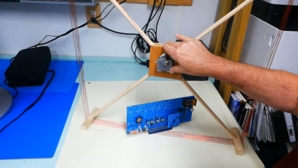
Continuing with the educational radio he’s talked about before,  he adds a loop antenna that is two feet on each side of a square, making it four square feet in area. Although he calls it an amplifier, it’s really just a passive tuned circuit that couples to the radio’s built-in antenna. There’s no actual connection between the antenna and the radio.

We aren’t sure if the reradiation explanation is really what’s happening, or if it is just transformer coupled to the main antenna. But either way, it seems to work well. You can think of this as adding a preselector to the existing radio. Loop antennas are directional, so this design could work as a direction finder.

We have seen many loop antennas, some with novel construction methods.  Some even tune themselves.

Continue reading “Antenna Pulls In AM Stations”

Building The Scoreboard Of Your Imagination

It might seem like electronic games and tabletop games are somewhat at odds. But there are always places where the lines are cleverly blurred as with this stat tracker beautifully constructed from a sandwich of circuit boards.

The nature of role playing games is one of deep imagination, putting yourself in the shoes of the player your are building though out a campaign. But of course the game board and pieces are there to keep track of all the data that your imagination just can’t. This can be done with a character card and some markers, a pad of paper, or a spreadsheet on your laptop. But to keep his mind in the world of Hyper Light Drifter, [Albert Phan] built this stat tracker that lives up to the aesthetic of the game.

The stackup of three PCBs does a brilliant job here, using cutouts on either end of the faceplate as a flexible tab that you press to actuate the surface mount button on the bottom PCB. The third PCB act as a spacer, not just for the six low-profile buttons, but also for the 40 LEDs that display status. That spacer has holes cut out for each light, providing isolation, with the FR4 substrate of the top plate acting as a diffuser.

It looks spectacular, it saves state between uses, and can be recharged via USB. But what’s that you say? You don’t play Hyper Light Drifter? Just respin the top PCB (and we suppose you’d need to tweak firmware as well) and you can swap it out for your game of choice.

Continue reading “Building The Scoreboard Of Your Imagination”

IBM Reveals POWER10 CPU Based On The OpenPOWER ISA 3.1 Specification

This week, IBM revealed their POWER10 CPU, which may not seem too exciting since it’s primarily aimed at big iron like mainframes and servers. The real news for most is that it is the first processor to be released that is based on the open Power ISA specification v3.1. This new version of the Power ISA adds a number of new instructions as well as the notion of optionality. It updates the v3.0 specification that was released in 2015, right after the founding of the OpenPOWER Foundation.

Currently, a number of open source designs for the Power ISA exists, including MicroWatt (Power v3.0, VHDL) and the similar ChiselWatt (written in Scala-based Chisel).  In June of this year, IBM also released the VHDL code for the IBM A2 processor on Github. This is a multi-core capable, 4-way multithreaded 64-bit design, with silicon-implementations running at up to 2.3 GHz and using the Power ISA v2.06 specification.

The ISA specifications and other relevant technical documentation can be obtained from the OpenPOWER website, such as for example the Power ISA v3.0B specification from 2017. The website also lists the current cores and communities around the Power ISA.

(Main image: POWER10 CPU, credit IBM)

Re-imagining The Crossed Gantry 3D Printer

Simply having a few go-to 3D printer motion system designs is no reason to stop exploring them, as even small iterations on an existing architecture can yield some tremendous improvements. In the last few months, both [Annex_Engineering] and [wesc23] have been piloting a rail-derived crossed gantry architecture, a “CroXY” as it’s come to be known. Borrowing concepts from Ultimaker’s crossed gantry using rods, the Hypercube Overkill project, and perhaps even each other, the results are two compact machine frames capable of beautiful prints at extremely high speeds–upwards of 400 mm/sec in [Annex_Engineering’s] case!

Both gantry designs take a rotated MGN12 rail (a la the Railcore) and cross two of them, mounting the carriage at the intersection point much like an Ultimaker. Each crossed rail controls a degree of freedom with vanilla Cartesian kinematics, but each degree of freedom also has a redundant motor for added torque. Like the CoreXY design, this setup is tailored for clean prints at high speeds since the motion-related motors have been removed from the moving mass. However the overall belt length has been reduced tremendously, resulting in a much stiffer setup.

But the innovation doesn’t stop there. Both gantries also feature a unique take on a removable Z probe. When the machine needs to level the bed, it travels to a corner to “quickdraw” a magnetically attached limit switch from a holster. Once mounted, this probe becomes the lowest point on the carriage, allowing the carriage to travel around the bed probing points. When finished, the probe simply slots back into its holster, and the print can begin.

Both [wesc23’s] CroXY and a variant of [Annex_Engineering’s] K2 are up on Github complete with bills of materials if you’re curious to poke into the finer details. With commercial 3D printer manufacturers spending the last few years in a race to the bottom, it’s exciting to still see new design pattern contributions that push for quality and performance. For more design patterns contributions, have a look at [Mark Rehorst’s] Kinematically coupled bed design.

Continue reading “Re-imagining The Crossed Gantry 3D Printer”

Building The Ultimate Raspberry Pi Automation Controller

At this point, we’ve lost count of how many automation projects we’ve seen with some variant of a Raspberry Pi at the helm. Which is hardly surprising, as the boards are cheap, powerful, and well documented. The list of reasons not to use one has never been very long, but with the PiCon One that [Frank] has been working on, it’s about to get even shorter.

The project takes the form of an IP65 industrial enclosure and support electronics that the Raspberry Pi Zero W plugs into. While expandable in nature, [Frank] has a core set of features he’s aiming for as a baseline such as additional serial ports, integrated uninterruptible power supply, a battery-backed Real Time Clock (RTC), an array of programmable status LEDs, and support for XBee and GPS plug-in modules. Feedback is provided through a pair of four digit seven-segment displays and a color 320×480 TFT screen running a custom user interface.

[Frank] envisions the PiCon One for use as a rugged solar power controller, eventually able to measure array output, energy consumption, and even operate motorized mounts to keep the panels pointed at the sun. To that end, he’s recently been experimenting with running JPL’s Horizon software on the Pi to determine the sun’s position in real-time. But the device is capable of so much more, and would make an ideal controller for many home and potentially even industrial applications.

Continue reading “Building The Ultimate Raspberry Pi Automation Controller”

How To Get Into Cars: Aero Mods For More Grip

In 1960, Enzo Ferrari said “Aerodynamics are for people who can’t build engines”. It’s a quote that’s been proven laughably wrong in decades since. Aerodynamics are a key consideration for anyone serious about performance in almost any branch of motorsport. Today, we’ll take a look at how aero influences the performance of your car, and what modifications you might undertake to improve things.

Gains To Be Had

Improving the aerodynamics of your vehicle can mean wildly different things, depending on what your end goal is. Aerodynamics affects everything from top speed, to fuel economy, to grip, and optimizing for these different attributes can take wildly different routes. Often, it’s necessary to find a balance between several competing factors, as improvements in one area can often be detrimental in another.

To understand aerodynamics with regards to cars, we need to know about the forces of lift (or downforce), and drag. Drag is the force that acts against the direction of motion, slowing a vehicle down. Lift is the force generated perpendicular to the direction of motion. In the context of flight, the lift force is generated upwards with respect to gravity, lofting planes into the air. In an automotive context, we very much prefer to stay on the ground. Wings and aerodynamic surfaces on cars are created to create lift in the opposite direction, pushing the vehicle downwards and creating more grip. We refer to this “downwards lift” as downforce.

Continue reading “How To Get Into Cars: Aero Mods For More Grip”

Automating Mini Blinds The Rental-Friendly Way

[Chris Mullins] wanted to automate opening and closing the slats of mini blinds in his apartment, and came up with a system to do it as a fun project. Manually opening and closing the slats means twisting a rod. Seems straightforward to automate that, but as usual when having to work around something that already exists, making no permanent alterations, complications arose.

The blinds are only 1 inch wide, leaving little room for mounting any sort of hardware. While there is a lot of prior art when it comes to automating blinds, nothing he found actually fit the situation [Chris] had, so he rolled his own.

The rod that is normally twisted to control the blinds is removed, and the shaft of a stepper motor takes its place. [Chris]’ mounting solution is made to fit blinds with narrow 1 inch tracks (existing projects he found relied on 2 inch tracks) and the 3D printed mount is fully adjustable, so the 28BYJ stepper motor can be moved into exactly the right position. Speaking of the stepper motor, the 28BYJ motor is unipolar but the A4988 driver he wanted to use is for bipolar steppers only. Luckily, cutting a trace on the motor’s PCB is all it takes to turn a unipolar motor into bipolar.

To drive the motor and provide wireless functionality, the whole thing works with a Wemos D1 ESP8266, an A4988 stepper driver, and a buck converter. While it worked fine as a one-off on a perfboard, [Chris] used the project as an opportunity to learn how to make a PCB using KiCad; the PCB project is here on GitHub and the ESP8266 runs the ESPHome firmware. Be sure to check out the project page on his blog for all the details; [Chris] links to all the resources there, and covers everything from a bill of materials to walking through configuration of ESPHome with integration into the open-source Home Assistant project.

Looking to control natural light but blinds aren’t your thing? Maybe consider automated curtains.