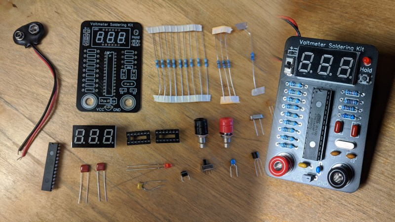
Unsatisfied with the standard fare of soldering practice kits that offer little to no purpose once they’re built, [Jim Heaney] decided to take matters into his own hands and design an easy-to-assemble kit for his class that, once put together, becomes the handiest of tools in any maker’s workbench: a functional voltmeter.
At the heart of the kit is a standard Atmega 328P microcontroller. While he could’ve picked something smaller or cheaper, not only does the bulky part make for easier soldering, [Jim] reasons that it’s a chip that’s easy to repurpose should his students want to build something like a breadboard Arduino, for example. The voltmeter has a fixed measurement range from 0 to 100 VDC, the only switches on the board are for powering it on and a hold button, which freezes the value currently being shown in the three-digit, seven-segment display.
Along with selling his kit to other makers and educators, [Jim] also hopes that his project encourages others to design similar soldering kits which favor some sort of function rather than getting binned once there’s solder on all the pads, as well as part variety and documentation. If you’re on the other end of the soldering spectrum, then why not challenge your skills soldering on a time limit?


What a fantastic idea! This looks like a great way to spread the word that soldering isn’t scary.
And the creator did a good job if they’re hoping that it encourages others; it’s definitely got me imagining one with an MSP430.
Very nicely done,
Thats a nice idea. Is Jim going to release the hard- and software sources? Or does he want to sell kits and we have to design our own open sourced version?
He has a kickstarter link in the project outline, although it’s just as bare as the project page. Even a short video would be useful.
In the FAQ he states: The code will be released at the conclusion of the Kickstarter, in both binary and .ino format.
I like it, I like it a lot.
That’s really a great idea. I’m not so sure about the “reuse it as an Arduino” part, since that would require a whole other PCB, in which case the ATmega328 is just a small fraction of the cost. What might have helped here would be including the footprint for a programming header (don’t even need to supply the header), so that all the student would need to add would be a $5 USB/serial adapter to reprogram it on the same board. This wouldn’t make it a full Arduino, but it WOULD be something that could be reprogrammed.
That was my first thought too, only thing missing is ISP header. Otherwise, it is brilliant kit. Easy to assemble, great for learning, and useful later. I like it, with or without ISP.
I designed a 328P board that I am including free of charge with each kit of the voltmeter I sell. My original plan was just to include all the extra parts, but like you said that can be a bit intimidating. Here is what the PCB looks like: https://i.imgur.com/uHcFx5w.png
Nice! Like an Arduino without the bells, whistles, and blinkenlights.
wouldn’t it make more sense to be in the 0.0 to 10.0 range? with all the exposed part and general usefulness? nice kit through to be sure.
Definitely, I do not suggest it for anything over 24V, the maximum of 100 just comes from the high-value resistor used in the divider. Its primary purpose was reverse voltage protection on the analog pins of the 328P.
Somewhere I still have the analogue multimeter I had to build in school, both voltage an ampere metering, with different taps for different ranges, that’s how most of them died…
Kids should have autoranging meters, and double insulated cases….
Former teacher here. The autorangjng on cheap meters sucks. The meter spends so much time hunting for the right range, the kid has no idea what they are measuring. And if the value is fluctuating a bit anyway, autoranging is useless. Let the kid think for two seconds about what they’re trying to measure, then work down the ranges until they get the most precision. I encourage those cheap meters based on that Intersil chip that was here on HaD recently. Oh and plenty of spare fuses!
This is a great idea! Well-done, Jim.
Why 000 to 100 Volts? The thing would be far more useful if it did 00.0V to 99.9V. Adding the decimal point reduces the total range by just 0.1V.The 328P’s on-die ADC can do this, and 7-segment LEDs already have a decimal point built-in. Being able to read tenths of Volts lets you measure far more things, like battery charge levels for example.
The range is 0.00 to 9.99, then 10.0 to 99.9 (although obviously you don’t want to measure that high). The decimal auto-adjusts to show the most accurate number it can.
@Jim Heaney said: “The range is 0.00 to 9.99, then 10.0 to 99.9 (although obviously you don’t want to measure that high). The decimal auto-adjusts to show the most accurate number it can.”
This is the first time I am hearing of two ranges and auto-ranging. Your article just says this:
“This is a voltmeter that is capable of measuring from 0 to 100V DC, using a 328P running an Arduino sketch.”
The HAD post parrots that, and more:
“The voltmeter has a fixed measurement range from 0 to 100 VDC…”
Noticed the author of the HAD article [Erin Pinheiro] added the words “…fixed measurement range…”
Another reply post that gets dumped to the bottom of the discussion thread. Sheeesh… This comment system is sooo buggy!