In the dawning of the IBM PC era, the computer case was a heavy, stout thing. These were industrial machines, built with beefy paddle power switches, and weighing as much as a ton of bricks. Painted in only the ugliest beige, they set the tone for PC design for the next couple of decades.
At the turn of the millennium, the winds of change swept through. The Apple iMac redefined the computer as a hip, cool device, and other manufacturers began to reconsider their product aesthetics. Around the same time, the casemodding scene took off in earnest, with adherents building ever wilder battle stations for internet clout and glory.
With all the development that has gone in the last 40 years of the PC platform, we’ve seen great change and improvement in almost every area. But in building a new rig this past month, this writer discovered there’s one element of the modern PC that’s still trapped in the past.
Ugly Little Headers

It’s the cases, yes. Sure, the modern PC builder has a wider selection to choose from than ever. Whether your predilection is for built-in acrylic windows or dazzling fans festooned with RGB LEDs, you can have your fill in the modern market. Connectivity options are better than ever too, with front panels overflowing with USB ports, audio sockets and even fancy drive caddies if you so desire.
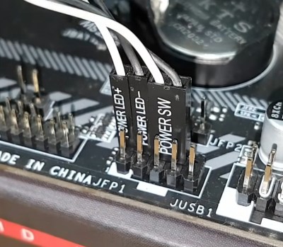
Despite this, the one thing that hasn’t changed is the ugly little headers used to connect the very basics of a computer case to the motherboard inside. Power and reset buttons, the internal case speaker, and status LEDs are all hooked up with fiddly little individual pin headers. With all the sophistication of a set of breadboard jumper wires, they’re a pain to install and an absolute joke on a platform that is otherwise at the cutting edge of computing technology.

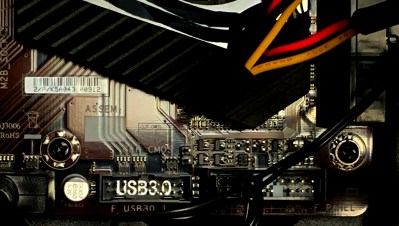
What’s worse is that there is absolutely no reason it should be this way. As it stands, motherboard manufacturers are free to lay out their connections for these features any way they like, often simply lumping a double-row pin header on to the board and putting a pinout in the manual. However, some manufacturers have gone to a higher level, using a moulded and keyed connector on the board. Despite this, they’re still intended for use with the aforementioned individual pin connectors, just making them harder and more fiddly to install. What is maddening is that these often sit right next to other connectors on the motherboard, like front-panel USB-3 connectors, or HD audio headers. In both of these cases, motherboard manufacturers were able to agree a common standard such that a single connector carrying all necessary signals could be used to hook the case ports up to the motherboard. They still use cheap, 0.1″ pitch header-style connectors, but they bundle all the wires into one compact, keyed package, making install a one-step process.

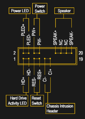
Why this hasn’t been done yet for power buttons and status LEDs absolutely escapes me. Thus, I propose a solution. A simple keyed header-style connector that carries all the basics for a PC case, that can be implemented on all PC motherboards going forward, and of course, all PC cases. This covers the Power LED and button, the reset button, the hard drive activity LED, the speaker, and a chassis intrusion switch.
The proposed solution, the Day Case Connector, if you will, is based loosely off a design already used by some motherboard manufacturers. If I’m honest, the diagram is largely cribbed from an existing motherboard manual with some extraneous “features” removed, because we’re trying to get this shipped, after all. Audio and USB connections are best left to the already-existing front panel connectors which work fine, and would only complicate things here. This is simply a basic standard for the barebones components in a PC case. Obviously, some cases do not implement reset buttons or speakers, but this is not an issue — they can be left unpopulated without interfering with the proper operation of the connector. Alternatively, mandate that every case have these features, and rule with an iron fist.
Obviously, a scathing op-ed isn’t going to be enough to make this happen overnight. You’ll need to help, by petitioning your local Congressman, Senator, or Girl Scout Troop, to get behind the cause. Only the people can affect real change at the end of the day, after all. Some may deride us, pointing out that for the average user who builds one PC every few years, it shouldn’t be an issue. They may point out that the time spent writing this article is longer than it took to install the headers anyway. These are mere distractions, and they must not stray us from our goal.
So please, next time you build a PC, do not throw your hands up in despair. Instead, let yourself be moved to action. We shall right this wrong before the decade is out — you have my word. Godspeed!


The real cable management issues (and this is what it boils down to, IMO) doesn’t start IN my PC but BEHIND it…
I was expecting the article to be a lament on the failure of the BTX form factor to kick the old ATX form factor to the curb.
BTX does have superior design for thermal management. I have said at times that the B is for “backwards” because it’s like a mirror image of ATX. ;)
When the PC was introduced, the chips on expansion cards were all on the right side (looking from the front). So naturally when whomever first tipped a desktop on end to save space did so, they tipped it up onto its left side. That put the expansion card chips on top so any heat they gave off would flow up and away from convection.
The VESA Local Bus extension to ISA had to keep the same orientation. EISA also had to, since the slots were also compatible with ISA cards. IBM’s MCA was also “right handed” because well, they invented the PC with its right handed ISA cards, why would they change it?
Then along came the PCI bus and its cards. LEFT HANDED cards that in a tower put the chips on the *bottom side*. Next to come was AGP, another backwards design, followed by PCI-X and PCI Express, also backwards like PCI and AGP.
Eventually those pushed ISA slots out completely, yet the ATX form factor remained almost unchanged (aside from its initial backwards power supply fan idiocy) and tower PCs still stood on their ‘left end’.
A few companies tried to market ATX towers that were inverted, with the power supply at the bottom, so all the expansion cards would be chip side up. Yet the majority continued to push left end cases with chips down.
The companies that designed BTX set out to fix all the problems with left end, chips down ATX towers. First off, the CPU would sit in the middle of the board with *nothing allowed* between it and the front or back of the case. That was to provide lots of free space for airflow, a large heat sink and a quieter, slower, larger fan at the back drawing air over the heat sink. The motherboard would mount to the left side of the case rather than how ATX and AT towers had it on the right side. The expansion slots and IO positions on the motherboards were swapped. That put the slots at the bottom, power supply up top, chips on the top sides of the cards. Since the main PCIe slot for a GPU was still closest to the CPU a card with a thicker heat sink could be installed without blocking the slot beside it.
Superior to ATX in all the essentials, correcting for all the issues caused by whomever thought it was a good idea to make PC opposite all other expansion cards. (IIRC even Apple’s NuBus had the same orientation as ISA.)
So of course the big OEMs decided to screw it up! They did things like making the I/O port openings a permanent part of the case, not providing an extra back panel slot next to the upper PCIe slot for 2x thick GPUs, using proprietary front panel connectors (Dell! Grrrr!) or power supply connectors (HP Elite! Grrrr!) and whatever else they could think of to kill off any 3rd party interest in manufacturing BTX motherboards for upgrading OEM computers.
That didn’t completely stop people from doing hacks on BTX boxen. One popular source for better BTX boards has been the HP Elite series of slimline desktops and towers, popular enough that premade ATX to Elite power supply adapter harnesses are available. With some work with metal cutting tools and DIYing the front panels stuff, it’s possible to stuff an Elite SFF board into an Optiplex tower case in order to be able to use full height PCIe cards.
But it would have been so much easier had the companies behind BTX told the OEMs they weren’t going to be allowed to get away with propritarizing BTX to ‘un-standardize’ the new standard.
Monitors and motherboards come and go, but three things in my computer system have not changed: My Cooler Master Cosmos case, Logitech G15 keyboard and MS Trackball Explorer. Well ok, four: Linux.
The fact is that manufacturers at least brand name ones don’t want standardisation they pursue the reverse. Look at an HP or a Dell mobo and this becomes all too evident
ASUS includes a thing in their higher-end boards, I think they call it a Q-connector. It’s just a pin header block with M and F pins. You plug all the case gibberish into it where you can read the damn labels and your fingers aren’t getting chewed up inside the case, then you take the big rectangular block and plug it into the mainboard. Bonus is if you lose the Q-connector or just don’t want to use it for some reason you can fall back to the ancient method of plugging the case wires straight onto the mainboard.
Actually there is a reason for this.
This way I can plug in only the start and reset button without the anoying LEDs.
And also this makes it super easy to make custom start and reset buttons.
True with a plug you’re forced to adapt to their idea of what a front panel should act like.
The reason they do this is for customizability purposes. Many motherboards and cases come with no speaker. Some don’t even have HDD LED’s. At the end of the day….if it isn’t broken, don’t fix it.
Also….side-note. if you think these are actually “difficult”, you should probably stop building PC’s. For that matter whe should hide all manner of sharp objects from you as well.
At one time long, long, long ago I had a motherboard and it came with a little plastic adapter for those pins. One side was male the other female. And it was about 5/16 tall not counting pin height. You could plug the front panel wires onto the adapter in the order they would be placed onto the mobo. Then you simply plugged the adapter onto the mobo pins in one easy step. Meaning you could do it outside of the case in both hands! Somewhere along the line I lost the little thing but it saved me much grief before I did. I found out it is a called a Q-connector (Asus) or 2×9 female header.