Once upon a time, 3D printing was more of a curiosity than a powerful tool, with many printing trinkets and tchotchkes rather than anything of real use. However, over the years as technology and techniques have progressed, we now see more application-ready builds. This water pump from [Let’s Print] is a great example.
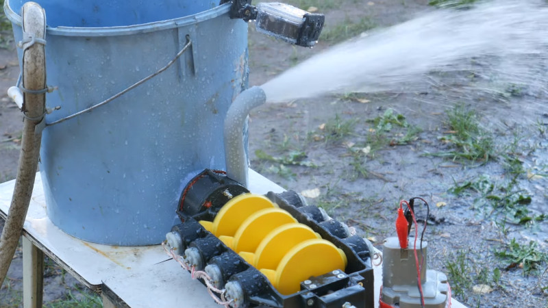
The pump consists of two major pieces – a drive unit, and an impeller. The drive unit consists of a gearbox that combines the power of eight electric motors, driving a single shaft. This is all achieved with striking yellow ABS gears in a black housing. The build video does a great job of explaining how to make the project work with different motors, and how to properly use the bolt adjuster to set the backlash on the gear train. The drive unit is then used to turn a 3D-printed impeller pump which is capable of delivering a great deal of water very quickly.
When fired up, the leaky assembly makes an awful racket and a huge mess, but sure as heck shifts a lot of water while it does so. Watching the water spray off the gears as it leaks through the bearings is a great sight, and it’s clear that the device works well. We’d love to see a cost and performance analysis of this pump versus a commercial offering.
While it’s certainly not the most rugged build, it’s a fun one that nevertheless gets the job done. We’d love to see this running a foam machine or a classic slip and slide. Video after the break.
[Thanks to Keith Olson for the tip!]


Interesting build. Some specs would be nice.
i’ll say it, instead of a gravity feed on it how about sucking it up instead. neat build but i can hit the bottom of a bucket of water with a hammer and drain it just as quickly with zero printing involved.
A bucket is a convenient container.
Furthermore, the capacity of a given type of bucket is most of the time is well known, so by measuring how fast it can empty said bucket, then it is possible to calculate flow rate.
Think of it as bench testing, but for a pump.
But the head provided by the water being above the pump intake is doing a substantial portion of the work no? Either way the thing looks pretty cool.
Not much more than 1 Bar.
https://youtu.be/yZwfcMSDBHs
1 bar would require a roughly 10 meter deep bucket.
Since the pressure generated is proportional to the weight of the pillar of water and the force provided by gravity.
And the force of gravity is roughly 9.8 m/s^2
The weigh of water is roughly 1000 kg per m^3
And if we accelerate 1 kg with 1 m/s^2, then we have a force of 1 N applied to it.
And 1 bar is equal to 100K Pa. Where on Pa is equal to 1 N/m^2
Thereby it will generate roughly 9.8 KPa for every meter of water.
Mercury on the other hand weighs 13534 kg/m^3, and would only need 75.2 cm of depth to reach 1 bar. (And that makes me wonder if a mercury based trompe would have been practical…)
Impeller pump is a centrifugal pump and needs to be filled with water for it to work. It can spin all day with its blades in air and won’t suck water from above the bucket.
When it is fed like it is shown, it’ll have no problems raising the water column above the level in the bucket.
I stand by my statement neat print but in this case a hammer would do the same thing. show it pumping water with some type of lift or else this video is worthless. even if it needs primed i don’t care.
Except: your hammer hole wouldn’t push the water up the exhaust pipe, turn it 90 degrees and then throw it across the grass.
Lift & throw maintained through lowering water level in the bucket.
The bucket is just the supply.
I’d like to see the exhaust pipe without the 90 degree turn at the end. Angle the straight pipe outward so the water isn’t falling back down onto the setup, or heat it up and give it a gentle bend with less resistance than that 90 angle.
Someone here has spotted the interesting effect of sharp turns.
And yes, a more gradual turn would be more efficient and make the flow loose less of its energy.
A sharp 90 degree turn has a surprising amount of flow resistance. Be it for water or air.
(We can put in vanes into the turn that helps direct the flow in the desired direction, and thereby reduce its resistance. A bit counter intuitive, but I don’t know how well that works for liquids, as an example water has a degree of self adhesion that makes it flow differently compared to gases. (grossly oversimplifying though.))
Anyone with a positive head shower pump will disagree with you on the usefulness of this setup.
So…with your hammer…do you not see some drawbacks to destroying the bucket?
“When all you have is a hammer, everything looks like a nail”
and some people can bend a crowbar in a sandpit….
It wouldn’t be such a simple test as you’d need to draw water up to prime (fill) the pump. The rotor would provide little suction with air so like most pumps wouldn’t self prime.
While it is a fun youtube watch. Talk about throwing efficiency out the window. Both economic efficiency and mechanical (oh and time as well). Just by a suitable motor for the pump. Or better yet. Buy a pump.
Said like somebody who has never lived on a remote island.
“Just buy what you need” and wait 3 months to get a box that’s not only been crushed, it evidently sat below somebody else’s crushed epoxy order. Wait 3 more for a new one.
This. Is. Hackaday.
🤣
8 small motors is ridiculous (unless that’s all you have). How ’bout just 1 beefy motor.
Exactly, here is the problem from a mechanical perspective.
1. All of those motors are unlikely to run at an absolutely identical speed so some of those motors are a drag on the system and others are doing most of the work. A single motor would be much more efficient here.
2. The multitude of gears add a lot of additional drag into the system vs a single gear or best yet a motor direct driving the shaft.
3. It would seem that multiple motor would be good for high torque however I would think that torque is not that important in this system. The most efficient operation is an impeller operating at its optimal designed speed. As long as you have enough torque to keep the impeller at its designed speed you are all set. Any addition of power is less efficient.
Your first point there is a bit of an incorrect assessment.
The setup uses brushed DC motors, they self commutat and mainly generates torque in relation to RPM.
Since they are all mechanically linked by the gears, they will all run at the same RPM.
Variations in the amount of windings and lamination quality of the core, and also the distance in the gap between the magnet and said core, not to mention the different sources of resistance. Will all effect the performance of each individual motor. Ie, how much torque/power it can generate at a given RPM.
But in a setup like this, the motors would all mostly work together as if they were one larger unit.
Yes, the “weaker” motors would do less of the total work. But unless we put in a motor that has wildly different RPM/V specs than the others, then we aren’t going to make any of them into a generator. (edge case would be if we run it with little to no load and start capping out on what the motors are able to reach in terms of RPM.)
In short, a Brushed DC motor will spin at X RPM at Y volts when under a small/insignificant load. As we increase the load, we will decrease the RPM and increase current consumption. Thereby doing load sharing between coupled motors of similar RPM/volt spec.
Brushless motors on the other hand is a different story.
But even there, a good Electronic Speed Controller (or VFD) should have the ability to regulate based on torque, and or power instead of pure RPM for each motor, we can still have a global RPM reading that we regulate based on.
So it is not inherent that a single larger motor would be more efficient.
Especially considering that larger motors have their own set of problems. Like typically having higher winding inductance, larger core losses, and more impacted by parasitic inductance in wiring, and also the good old skin effect.
A cluster of smaller motors also have their own set of issues, like needing more gearing (that also have losses of their own), having more points of failure due to having more parts.
So it isn’t a clear cut if 1 large motor is better than 8 small ones or not.
Also, 8 small ones have the advantage that one can start one motor after another, staggering their start and thereby reducing peak current. (This is though not implemented in the setup shown in the article.)
I would also not worry too much about gear related losses.
The gear used is relatively efficient as far as friction goes, and with some lubrication it will most likely have little friction to be all that meaningful. (I can be brave and say that it is at most only loosing 1-2%.)
One motor direct drive on the impeller would be fine. What am I missing? Is this guy really Rube Goldberg?
Ugh. Now you have me thinking about trying to print a replacement pump for the gas-powered power washer I happen to have lying around which has a working engine but broken pump. Just what I needed. Another project idea!
Much different on the power washer because your pressures are much higher there. This pumps is not working against much pressure. Don’t think a 3D printed part would hold at 2k PSI plus ranges. Impeller pumps are optimized for flow, you need a gear or vane type pump to build high pressures.
“This project in its current form would not help me in my personal situation and is therefore useless and a waste of time!”
How about a turbine instead? Get enough hydrostatic head and a fistful of rectifiers/voltage regulators and you could have an 8-station charging system.
You’ve got me thinking I could build something to harvest energy from my wastewater to power batteries…