At some time or another, we’ve all had an idea we thought was so clever that we jumped on the Internet to see if somebody else had already come up with it. Most of the time, they have. But on the off chance that you can’t find any signs of it online, you’re left with basically two possible conclusions. Either you’re about to enter uncharted territory, or your idea is so bad that everyone has collectively dismissed it already.
Which is precisely where [James Stanley] recently found himself. He had an idea for an non-contact optical sensor which would detect when his racing mower was about to run out of gas by analyzing light passed through a clear section of fuel hose. He couldn’t find any previous DIY examples of such a device, nor did there appear to be a commercial version. But did that mean it wouldn’t work, or that nobody had ever tried before?
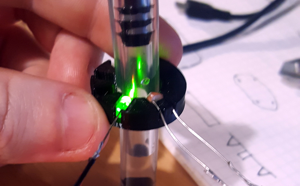
Before he fully committed to designing the sensor, [James] started out by doing some proof of concept experiments. The first step was 3D printing a ring that had openings to slot in a LED and photoresistor at different angles to each other. Putting the LED and sensor on opposite sides of the fuel line makes the most logical sense, but he wanted to test if it really returned the strongest signal. Surprisingly this little test indicated that the best alignment was actually 60°, as it produced the largest gap between the “fuel” and “no fuel” readings.
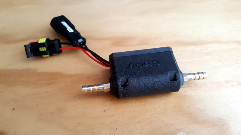
Confident that the idea had merit, [James] pushed ahead and designed the 3D printed enclosure for what he’d ultimately dub the FuelSafe. He also came up with a relatively simple circuit using the ATtiny85 that he put together on a piece of perfboard. The MCU reads the value from the photoresistor, compares it to predetermined threshold values, and produces a digital signal to indicate whether or not there’s any fuel visible in the line. This signal is ultimately used to light a LED on the dashboard to indicate when it’s time to pull over and refuel.
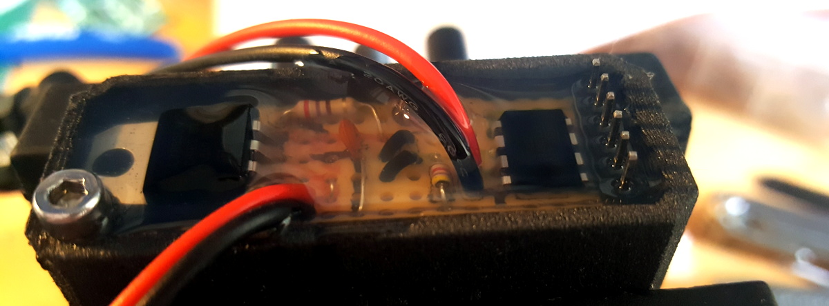
To make sure his newly crafted sensor would survive, he even went as far as potting the whole thing with a two-part silicone resin. Unfortunately, while it might look impressive, [James] notes it was the wrong material to use as its far too soft and doesn’t really stick very well. Still, with the sensor housing all buttoned up, it should at least provide some cushioning to help with the sort of wild vibrations that we assume must go hand in hand with racing lawn mowers.
We’ve seen hackers put together fuel monitoring systems before, though out of an abundance of caution they’ve always used off-the-shelf sensors. But we think [James] has shown that if you do the research and put in the design effort, it’s possible to build your own fuel sensor that’s as safe as anything on the commercial market. Now we just have to wait for COVID-19 to blow over so he can get out to the track and see how well it works.


What is the likelihood of the plastic tube aging and changing color or even getting fuel deposits on it? If there’s enough of a threshold to deal with that over a few years then no harm, no foul. Otherwise a small glass section might be warranted.
Nice hack.
You had me at racing lawnmower.
Me too. In fact I am still in the fog. I didn’t know there were such things! Are there competitions with fastest times to mow an entire acre and such, or is it all about acceleration like a drag strip. Hungry minds want to know.
The world is full of surprises.
More than that, there are circuit courses, (lawn)tractor pulls, and all sorts of other events.
There are even sanctioning bodies like The United States Lawn Mower Racing Association (LetsMow.com)
+1. Obligatory xkcd.
Back home it was called grasscar
The 12 hours of Le Lawns
I’m interested in a way of implementing this for measure readout. I have a vintage BMW motorcycle and have been trying to think of a way to add a digital fuel sensor, was thinking optical read of a captive float.
Could multiples of this be chained at specific points for live fuel readout?
Or perhaps an inline hydrostatic presure sensor for live readout?
I’ve been planning to add a fuel gauge to my son’s ATV (Polaris RZR 170), and the solution I think I’ve arrived at is a float connected to a rotating pivot. On the pivot would be a magnet, who’s orientation would be read by a hall sensor. I’ve played with a high resolution hall sensor, and it should be plenty sensitive enough to read a roughly 30 to 40 degree rotation with enough resolution to show at least 8 levels between full and empty.
The nice part about this would be that the float/pivot/magnet could be entirely sealed within the tank, and read through the wall or some plug in the wall. I have considered optically reading a float down a tube, and it generally worked in testing, but it would probably need to be sealed off from the inside of the tank. I just don’t trust my electrical designs and component selections being exposed to highly combustible fumes and fuels.
this operates on the same principle as spiral-float-needle gas-cap fuel gauges use – cork on a twisted metal strip, riding on two guide rods. they’re often the primary point of failure in machines left outside as the plastic window over the needle rots out from UV damage, letting rain get into the tank. so you could take one of those and whack the fallible gas cap element off and add your rotary sensor. heck, you could probably tack it onto the back of a standard gascap
This is why I love this site, the comments are a trove. I was trying to think of a way to use the posted hack to monitor my maple syrup pans (picturing a glass tube on two elbows welded to the pan), but if the syrup level drops below the sensor scum will dirty up the tube pretty badly. Then comes this bit of motorcycle knowledge I’d likely have never found on my own.
Interesting. I like the idea of a hydrostatic sensor a little more now because I can get an exact amount of gas currently in the bike simply by pressure. Hopefully to go to a small Arduino controlled MPG calculator or something.
For, I have seen a guy do custom hidden digital speedos blended into an expoxy filled and smoothed hole in the tank. athe tank is black, but the fuel gauge shines through a few layers of clearcoat on a small part of the tank if you know where to look.
So there is definitely a fuel impervious clear expoxy made by someone, or this guy’s idea would never have worked. I’ve never seen anyone else do anything like it.
Use the principle of a sight glass. A clear tube connected to the top and bottom of a tank by 90 degree fittings. While normally placed vertically, it wouldn’t have to be. A number of these sensors could be placed along a tube, just far enough apart for the light from one to not bleed over into the others, then put the tube on the tank at enough of an angle to make it fit. Have the outputs of the sensors run to an LED bar graph.
Sight glass idea has been done before- I’ve seen it on custom bikes plenty but I have no intention of chopping up an antique fuel tank that is not exactly easy to find.
I am looking for a non-destructive method in my case.
My first thought reading the article was to apply it to my boiler’s sight glass (which I didn’t know the term for, so thanks for that).
I believe there are photointerrupters designed for just this purpose. For example:
https://www.digikey.com/en/products/detail/tt-electronics-optek-technology/OPB350L250/1007900
They aren’t all-in-one modules — you’d still need to add a microprocessor — but they’re purpose-built for fuel detection, come with a molded housing that snaps on to a fuel line (there are several sizes available), and there are reference circuits and firmware available for using it just as he proposes (https://www.ttelectronics.com/TTElectronics/media/ProductFiles/Optoelectronics/Datasheets/OPB350.pdf)
Yes, this method is used for detecting air bubbles in things like IV lines because the sensor is reusable.
One way to do fuel level is to use an ultra-sound-based distance sensor to detect the level of fuel in the tank. For something like this, where the level is moving, you would have to do some averaging. That’s how a lot of fuel levels in underground gas tanks are monitored — nothing touches the gas, so no chance of explosion.
That reminds me of some silliness that I saw recently where some improbable fuel level detection methods were suggested (mostly in the comments).
https://www.halfbakery.com/idea/And_20miles_3f_20to_20go
The commerical fuel level sensors just have a magnet on a float that rides up and down a pcb with hall sensors on.
Hmmm, now that’s a pretty simple approach! I’ll have to rethink my idea. Could do a really thin PCB with the hall sensors, put it in a plastic tube, and use a ring magnet on a float, so it rides up and down the plastic tube.
Maybe won’t need a comparatively heavy magnet, the setup could be made sensitive enough to detect a small fridge magnet, just put it in something to make sure it floats and without catching on anything ie enough room between the floating fridge bob and tube.
You could even go without a magnet by just using a shorted multi turn enamel fine wire coil inside a floating piece of plastic, though that makes the drive/sense coils and filtering a wee bit more complex…
That sounds exactly like the dielectric oil level float on the Agie Charmille EDMs I ran. Round tubular black plastic ring, around a round brass tube with I assume a hall effect sensor in it.
Constantly got jammed though by EDM metal sludge buildup keeping float from sliding on the rod.
Thanks for post :-)
Been musing on the design of a novel sensor few years ago for diesel fuel quality as it’s useful to know water content and if any bacterial buildup. There are a few consequences leaving diesel for a long time without running engine as I understand diesel slightly hygroscopic as in absorbs some moisture from air and some bacteria species can survive and over time release their waste which causes a gum or varnish type buildup, though can take a few years and depends on how well the tank is vented.
I wonder if for larger & older engines like the 11L displacement bus engines in Australia with earlier mechanical distribution systems that there is a pressure regulator return to tank – which I guess would vent rather hot fuel, since pressures high, killing the bacteria eventually. Thus running the engine each few months for a few minutes would reduce bacterial load And hopefully if any gum did build up then the higher temperature and higher density of gum vs diesel would offer some incremental purging too as the gum rich fuel would settle to bottom assuming not always perfectly mixed…
Anyone come across this issue – occurs to ask if any chemical additive ideas eg to “convert” the diesel gum/bacteria in tank so it can be consumed without having to outright flush tank, thanks ?
The (gum) problem can be solved by using “winter” diesel or the otherway of mixing 20:1 gasoline with the diesel. Learned that in the army when the temperature is lowing low then the “summer” diesel starts doing that.
Yeah that would help, that ratio seems safe positioning. Just pulled the old diesel out, bit frothy and darker. Over here in Perth, Western Australia it only gets to 7C in winter evenings, days 12C rarely that low often 15C or so, summers 45C days and 22C evenings, so guess we often have ‘summer’ diesel… I understand I can feed back the frothy diesel with fresh in small ratio and as long as not left in tank ie used up quickly, to use it up over time or maybe add some antibiotic which binds to the bacteria protein to precipitate it out then decant before using.
I wonder if a surface transducer put on the outside of the gas tank and a microphone, also pressed to the tank, couldn’t detect an empty (or nearly so) tank by the sound of it. It would be non-invasive which is desirable.
Good idea MacAttack,
Straightforward to calibrate, start with empty tank then add few litres at a time noting spectral signal changes each time, eg ah lah Fourier proceased signal from microphone into a weighting network like maybe some Kalman filter aspects too, of course put through appropriate bandpass filter derived from transducer specs as a starting point. Might have to experiment with transducer vs microphone locations, opposite side midpoints might be a start or both at lowest might be best as reflections all over the tank and wouldn’t want the microphone or transducer operating ‘dry’ is so have range of readings not sudden change if either were to go from liquid to vapour ;-) Heck both can be on underneath it feasible but far apart…
You dont even need a micrphone. Just glue a piezo transducer to the tank bottom. The resonant frequency will change depending on if it is empty or not. Pulse and read the return signal.
Heck that’s a good idea too, though I wonder on the comparative sensitivity and bandwidth as the transducing element heavier in general than a piezoelectric microphone of useful frequency response ?
If this works, this sounds plausible to solving my problem.
I will try out this method to determine the color of urine and suggest if the person should drink more water.
If you put this between tank and engine, you will only know few moments before you actualy run of of the gas. So what is the point? Might as well just wait till your engine stops and refuel. Few extra ml of fuel in the tube will not add you any benefits. Except when your main concern is not to allow air bubbles entering the engine. In such case you should install kill-switch relay to stop the engine when there is no gas in the tube. That would make more sense than having LED indicator minute bofere engine running out of gas.
I was thinking about that as well. I suspect a lot of the ideas proposed will suffer from some inaccuracy when the level gets low, if only due to motion. One “easy” fix would be to have 2 “tanks”, a main and a smaller secondary downstream. When there’s no flow for X secs in the tube inbetween, or it reads empty for X secs in the main, then it’s time to pit and refuel. The secondary “tank” might even just be a length of fuel line and/or a fuel filter. Whatever is needed to give the user enough time to react in a normal (for lawnmower racing) manner.
Over the years I have stripped down an awful lot of medical equipment and most of it has the requirement for detecting air bubbles in a line of fluid (usually blood or IV drip etc). This is almost universally done using a small ultrasonic coil on each side of the tube, pressed snugly against it with spring loaded jaws / no air gap between tube and sensor. A circuit simple sends a low power ultrasonic pulse into the fluid and the magnitude of it being detected on the opposing coil is your fluid presence indicator…
I think some dialysis machines I parted out even had this implimented on a small PCB in descrete logic / analogue opampery. Hunt for air bubble detection circuits, that should yield plenty of patents and references for this, if you want an alternative method. Only problem is it may require fairly soft and malliable tubing…