[Dan Royer] shared a tip about how to get a reliably tight fit between 3D printed parts and other hardware (like bearings, for example.) He suggests using crush ribs, a tried-and-true solution borrowed from the world of injection molding and repurposed with 3D printing in mind. Before we explain the solution, let’s first look at the problem a little more closely.
Imagine one wishes to press-fit a bearing into a hole. If that hole isn’t just the right size, the bearing won’t be held snugly. If the hole is a little too big, the bearing is loose. Too small, and the bearing won’t fit at all. Since a 0.1 mm difference can have a noticeable effect on how loose or snug a fit is, it’s important to get it right.
For a 3D printed object, a hole designed with a diameter of 20 mm (for example) will come out slightly different when printed. The usual way around this is to adjust printer settings or modify the object until the magic combination that yields exactly the right outcome is found, also known as the Goldilocks approach. However, this means the 3D model only comes out right on a specific printer, which is a problem for a design that is meant to be shared. Since [Dan] works on robots with 3D printed elements, finding a solution to this problem was particularly important.
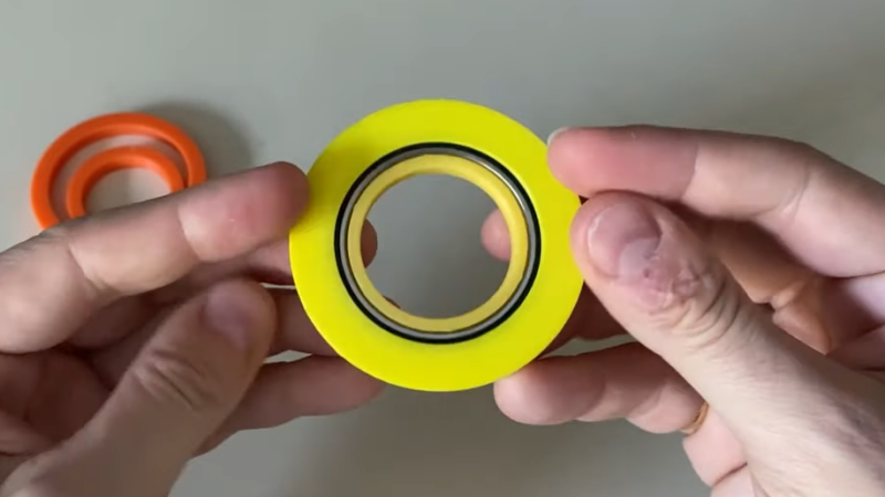
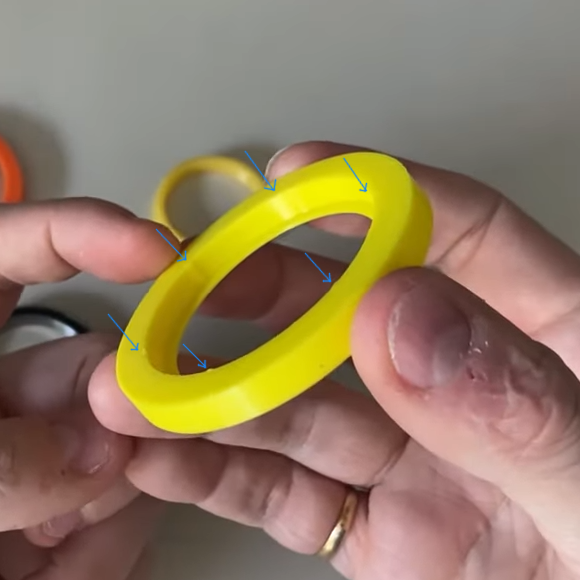
The solution he borrowed from the world of injection molding is to use crush ribs, which can be thought of as a set of very small standoffs that deform as a part is press-fit into them. Instead of a piece of hardware making contact with the entire inside surface of a hole, it makes contact only with the crush ribs. Press fitting a part into crush ribs is far easier (and more forgiving) than trying to get the entire mating surface exactly right.
Using crush ribs in this way is a bit of a hack since their original purpose in injection molding is somewhat different. Walls in injection-molded parts are rarely truly flat, because that makes them harder to eject from a mold. Surfaces therefore have a slight cant to them, which is called a draft. This slight angle means that press fitting parts becomes a problem, because any injection-molded hole will have slanted sides. The solution is crush ribs, which — unlike the walls — are modeled straight. The ribs are small enough that they don’t have an issue with sticking in the mold, and provide the mating surface that a press-fit piece of hardware requires. [Dan] has a short video about applying this technique to 3D printed objects, embedded below.
Designing around a manufacturing method’s limitations is key to getting good results, and techniques from one area can cross-pollinate with another, as they did here. Whether you’re just curious, or experimenting with something like hot-glue injection molding, it’s worth spending a little time to learn more about injection molding and its design considerations because it’s one of those technologies that makes the world go round.


I always thought that the point of these crush ribs was to use impart a certain springiness into the fit. For example, if a pen cap has three crush ribs, then the round cap will deform to become slightly triangular as you put it on. This keeps the cap squeezing on the pen so you get a better force profile. If there were no springy deformation, then it would be too tight or too loose.
I think if the ribs crush, they’re crush ribs, and if they don’t, they’re springy.
spring ribs?
Happens to ribs soaked in vinegar
This is imparting springiness with a larger value of the spring constant.
This is kinda a different issue. Plastics in general do not like something called Hoop stress, The knit lines will fail with hoop stress. Trilobula plastic screws are designed to minimize this by being slightly triangular, they deform the circle of the hole into a slightly triangular shape without generating the hoop stress which will cause cracking and failure.
seems like it would wear those nubs out when being so near a bearing thats getting a load put on it.
I think so too, you’d need a lot more of them so when they crush the material would spread out in many places and would have nowhere to go. I just provide the source files, usually Fusion360 or something ‘free’ and use parameters to people can change tolerances easily.
Especially when there is an additional heat load. I have seen a defunct Dewalt oscillatory grinder, which did not have a motor frame, but stator and bearings were separately press fit into the plastic housing (Nylon, 30% GF). There ere similar ribs and they were deformed by heat – which of course let the bearings get out of alignment and so the load on the motor increased even more -> more heat until the thing burned out.
This is the main point about using crush ribs, you have to keep in mind that the load bearing surface of the bearing to part interface is now reduced only to the small lines of the crush ribs. If you have a low load application this could be fine. If you are running a high load, you’ll likely crush those ribs further, and your bearing is no longer tightly held, with all the problems that that causes.
Maybe useful to some folks, “tolerance rings” are basically this for metal parts.
They’re a rolled, wavy steel band that can take up variation in OD/ID on mating cylindrical parts (like a bearing in a bore, or gear on a shaft), so you can reduce the tolerance requirements between the mating parts, and reduce the effects of differential thermal expansion on the interference.
I would like to use this but I probably could not stand those ribs being crushed like that.
I’ve done similar things in projects with my laser cutting machine. In the CAD add small, sharp indentations inside the circular hole; laser-cut it from acrylic (or MDF) and press in the bearing or whatever. On the first insert operation those indentations wear down to make a good fit. Not suitable for repeated (dis-)assembly.
Definitely a mounting method to test out on some scrap before using it in larger objects.
For flexible parts a nice solution is to make a slightly oval shaped hole, so as the bearing/motor/whatever is pressed in, the hole is conformed to the shape and the contact area is still relatively big.
Discovered that trick while operating old and janky CNC machines.
As many have mentioned, if the bore is holding a bearing, then the crush ribs will be all that’s holding it and bad things will likely happen. However, there is a good application for crush ribs that I have used. If you need to assemble two 3D parts together without glue, make a peg in one and a slightly smaller hole with crush ribs (I usually include three small domes in the bore) in the other and press the parts together. For bearings I usually do a test print or two to get within about a thou of the right diameter. Then use a vice (with protected jaws) to insert the bearing.
I’ve run into tolerancing issues, but honestly I just print test pieces until I get the fit where I want it, then make the final version. Iterative design is the meat and potatoes of 3D printing
Love this post! I design publicly accessible 3D models for others to print. I have no idea how accurate their printer will be , and therefore, how much clearance I need to add to articulating parts. This is a tool that I’ll be sure to add to my toolbox and use going forward! Does anyone know of a repository of ideas like this – specifically for 3D models for 3D printing?
Hey Donald, here’s a much-requested follow up: https://www.youtube.com/watch?v=kJ_ukmL5Uls