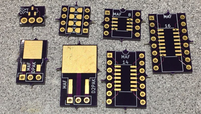
If you need to add one or two SMT chips to your breadboarded prototype, [Travis Hein] has you covered. He designed a set of small SMD adaptor boards for various SOIC, SOT23, and DPAC patterns using KiCad. He has released them as open source, so you can feel free to use them or modify them as needed.
Normally we don’t see people bypassing the schematics when designing a PCB. But we can agree that [Travis] has found a situation where going direct to PCB makes more sense. He just plops down the package in Pcbnew, adds some pin headers and wires everything up directly on the PCB. (But don’t worry, some of you may remember [Travis] from his earlier SSR mains switching project, which demonstrates that he can indeed draw proper schematics.) We know there are more people out there who prefer to go straight to PCB layout… [mikeselectricstuff] comes to mind. If you could yourself among this tribe, let use know your reasoning in the comments below.
We wrote about a similar universal breakout boards for SMD parts back in 2016, which is a single breakout board for two- and three-pin jelly-bean components. If you paired some of those boards with [Travis]’s breakout boards, it would make a great combination to keep in your prototyping gadgets bin. Consider this project the next time your favorite PCB shop has a sale.


I used machine socket and solder SOIC parts on top with individual strands of wire. SOIC is 0.05″ pitch, so it is very easy.
If you don’t have machine sockets, then just mask the hole for a protoboard and use header pins. I like the finer machine socket pins as they don’t damage regular IC sockets like headers do.
Good idea. Surface mount components and breadboards can live together, as long as the frequencies aren’t too high. The break-away areas are unpleasing.
That’s what metal files are for.
I’m must be missing something. These can be bought really cheaply online, right?
Yeah, there are links in the repo for purchasing from Oshpark.
Of course there are plenty of SMD breakout boards out there to be purchased. I took the article as a reminder that in KiCAD (and maybe some other EDAs) you can skip setting up a schematic and instead just layout the footprint & traces since there isn’t a netlist to worry about. Seems like a way to save time in avoiding setting up a meaningless schematic symbol and netlist (for this use case).
every EDA package lets you skip the schematic part of it, just have to disable rules
In fact I would bet that’s most peoples introduction of EDA packages, I already have a have a working circuit, I just want a PCB without redoing the thing from schematic level
There are indeed lots of adapters…. But if you’ve never tried to use them many are poorly designed and not conducive to using with a breadboard.
Indeed, there are. I’m not sure I see the novelty of this. These are available from a wide range of sources.
With OSHPark in the US, you can design small breakouts for anything you can imagine and get them made for $5 a square inch. A SOIC 14 adaptor will cost a couple of bucks.
and with china suppliers and a panel layout you can have like 200 made for 10 for the same lead time (dunno why osh park is so popular)
Okay, how many of us have made our own versions of these? [raises hand]
https://oshpark.com/shared_projects/OnBeTW0s
https://oshpark.com/shared_projects/CgAelWzD
Yes, we all have at least one drawerful of these and they’re a good project to use for learning/teaching an EDA suite. Is it really a hack, though?
Here’s a fun project that you can try along the same lines: size the plated holes to fit neodymium disc magnets, and make your own snap-together circuits using coated metal surfaces as breadboards.
You can solder the nickel coating without destroying the magnet if you’re quick and cover as much of the disc as possible with ferrous material while it is being heated.
why, you are reinventing the wheel that has the same issues + more than what’s been established
Because it’s fun and interesting? Hacks aren’t about efficiency…
This is really cool! On some there is a trace that goes under by vias to some little pads. Are those for more components like resistors or something? I’m not entirely sure what those are for. The one with eight pins says “IC OPAMP” on one side and “MAF 8” on the other. Does that mean it is double sided and you flip it over for each kind or do you need an “OPAMP” under the “MAF 8” and connected to those pins?
just use the side that fits the part
Inventing the weel….
It´s over 10 years i buy such adapter 0.1″ raster PCB for SMD parts.
Why bother doing it again and again ?
Open source and it also catches the eyes of people new to the field.
I used a similar breakout from Ali to flash the CH552G:
http://www.zoobab.com/ch552g-blink
Trouble with these is you cant get bypass capacitors close enough to power and ground pins.
They work for many IC’s but for parts with fast rise time I wouldn’t use them.
Look on the underside of the boards. They might not be placed correctly for all parts, but there are pads for a cap on the common VDD/GND pins.
Though if you’re using parts fast enough that a decoupling cap plugged into the breadboard straddling the chip isn’t good enough, the rest of the breadboard parasitics are probably going to make life interesting. It’s nice to have the cap permanently attached in any case, so you have one less part to go hunting for.
Alright, I sure do appreciate this. I’m in exactly this boat right now. Have chips to play with, but the breakout boards are $8/pc, which is almost twice the cost of the chip. Stupid! If I just want to play with the chip, it’s too much to design a whole board. I can design a breakout board quick, and it brings it down to less than $5 each. Plus, I can plop those caps right next to the chip now that snarky sparky raised that point. 👍