Electret microphones are capable of high-quality output, and are prized for their smooth frequency response. However, unlike other types, they can’t simply be plugged directly into a mixing desk. Instead, they require special high-impedence circuitry to extract the audio signal for recording. [DJJules] is a big fan of these microphones, and decided to build a high-quality, easy to use circuit that he has shared with the community.
The goal of the project was to create a circuit to match the TSB2555B electret capsule that could be used with phantom power, and that could be built with easily obtainable parts. [DJJules] had used FETs in the past, but grew tired of routinely having to hunt for obsolete parts. Instead, this design relies on a dual OPA1642 op-amp, with its low quiescent current meaning it’s perfect for running off phantom power. This means the microphone needs no batteries, and using a dual op-amp enables the circuit to properly drive a balanced audio connection.
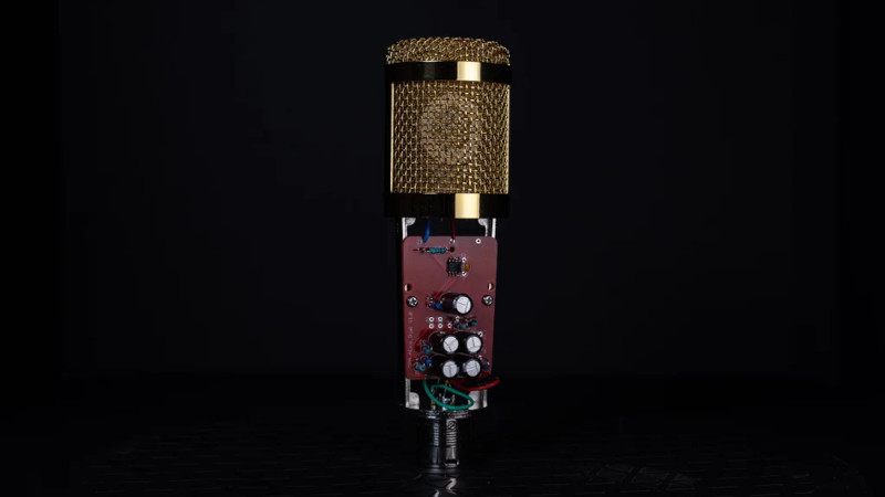
The circuit is designed to fit inside a common BM700 or BM800 microphone body, and the PCB can be ordered from PCBWay for those interested in building their own. There’s also a saddle on Shapeways that’s designed to neatly mount the electret capsule within the housing.
The final results are impressive, and this project would make a great entry into the DIY microphone space for anyone eager to start building their own gear. Of course, there are simpler builds if you’re looking for an easier way to get started. Video after the break.


Huh. I didn’t know about the TSB2555B or Transound for that matter. That’s a pretty large electret capsule.
Taking the non-inverting signal and then inverting it, does that not introduce a phase delay?
Is there a reason not to take the input signal and split that to feed into an inverting amp and a separate non inverting amp of the same gain?
Just curious. Looks like a real nice design.
According to datasheet the op-amp shifts phase by 90 degrees up to 250kHz, if I’m reading the graph correctly. Slightly more below 50Hz. So the inverted output is 90 degrees out of phase. Correctly the pin 6 should be connected to pin 3, not pin 1…
No, you’re misunderstanding it. The amplifier in open loop operation has a phase shift of 90 degrees, but it also has a massive amount of gain (~100 dB, 100000x, which would vary drastically between parts) that would cause it to be basically unusable for audio applications. That’s why there’s feedback, to force the output to correspond to the function you want to to perform rather than the base characteristics of the op amp instead. The phase shift and all that kind of stuff really only matters if you need good op amp characteristics at high frequencies, where the gain drops off and you start having to worry about it, which isn’t the case here with a DC to 20 kHz BW audio signal
Note that Figure 5 looks weird at first glance since it shows the “open-loop” gain and shift, and both op-amps here are used closed-loop in this circuit. In this case, shift is zero for DC through audio frequencies (and well above – like 1MHz). If this weren’t true, it would be the world’s worst op-amp. Take for example Figure 12. That shows a unity-gain signal at 500kHz and there’s no shift.
Also, one can’t connect pin 6 to pin 3 as that would effectively short the mic input to the virtual ground. If you put the resistor shown between 6 and 1 back in between pins 6 and 3, then the input impedance will be that of the resistor. And of course that’s too low. So the circuit looks fine, though I don’t disagree that the two 2.2K resistors for unity gain could be larger. I think just he did that just because a nicer value is probably closer to 2.2K than 47K, and the 2.2K was already in the BOM so he reused those.
Overall, I really like this design and will likely be building one myself.
Gary, Kelvin Ly, you are right. My bad – I didn’t have enough coffee this morning, so I made rather basic mistakes…
looks like a differential output. Balenced with respect to ground. And don’t lower resistor values have less voltage noise. So 2.2k might be chosen for low noise.
That’s the first time Ive ever seen a 1G ohm in a low voltage circuit. Could be humidity sensitive. Also, in a low power design, why use 2k2s on the inversion circuit? A much higher value would work just as well without burning up power.
Usually electret microphones have an internal JFET for impedance matching and as first gain stage in case of TSB165A. However this guy bypasses it so he needs much higher input impedance for no real gain, pardon the pun. Actually this makes the microphone worse, because (as you mentioned) it will be sensitive to external conditions…
As for inverting part, he connected it wrong, which I explained above, and with JFET inputs on these op-amps he could go with 10-100 times bigger resistors…
you can (and should) deal with that by first thoroughly cleaning the board and all connections after soldering, to get rid of solder flux and any other dirt, then painting at least the input side of the board with shellac, epoxy or another high-resistance waterproof coating.
I was a little surprised that an input with impedance that high didn’t have a guard ring as well.
Almost all cold solder joints.
Nice design. Low solder skills.
Non Lead Solder often looks like cold solder joints. Might be that
I say it’s cold solder because of the times.
He doesn’t let the flux do the job.
This project sparked my interest.
BUT: the company selling the microphone capsules goes crazy.
Each capsule is 13$US, but shipping to abroad trough UPS costs at least 43$ (before taxes).
Stupid.
If You really want it, go through MyUS.
Create a dummy address located in SFC.
They will repackage if possible and ship at MUCH lower costs to the EU I’m living in.
The capsules look like cheap chinese stuff, the datasheets are completely neutral. You might find these electrets at Aliexpress and similar sources for much less.
Have you tried any of these electret mic capsules – noname or otherwise? Homegrown mics using Transsound capsules like the TSB2555B and an active balanced output circuit are holding their own with commercial mics costing north of a hundred or two. Lots of writeups and sample recordings on the web. So paying $13 for the right capsule seems like a pretty good deal to me. (I bought a bunch a few years ago)
There are lookalike capsules on AliExpress… but I’ll let someone else find out if they’re as good or not.
Transound is a chinese manufacturer. It make no sense to buy from a US reseller if you live in the EU.
Agreed… if there is such a source. Transsound mainly sells their electret capsules to manufacturers of pro mics. Their mic capsules were hard for the DIYer or experimenter to get, until a company in the US bought them in quantity and then offered to sell them individually to us nerds.
I had the same issue with Primo electret capsules – the only place I could get some from is in the UK.
Yes you can find many electret capsules on Aliexpress and other sites, but so far none of them are known to be from Transound or another respected maker. And counterfeiting is not unheard of…
Transound capsules are NOT ‘cheap’ or junk. If you want to build a better mic, they’re worth the price and hassle.
I am from China,which we made many capasules, and you can buy Transsound capsules from me
Nice article. I’ve seen the popular all-transistor ‘Alice’ circuit used by many mic-builders, but this is the first time I’ve seen just opamps used. I have a small stock of Transsound electret capsules, so i hope to give this a try this winter. Mics are great ‘lockdown’ projects :-)
btw – to DIY some amazing low-noise omnidirectional mics, google ‘Primo EM272’. I have a few of the EM172’s (previous version) and they’re great.
It’s so easy to critise someones work, can you do better? If you can, spend hours buildiing it , posting it to the’net
Hello, it may not be the right place to ask here but any direction would help: does anybody know how to build a car microphone to replace the original built in, that can cancel the road and car noises and maybe amplify the voice? Thank you so much!
Cancel? No. Move the mic closer.
Hi, I am very satisfied with my two rebuilt BM800s using TSSB2550B capsules and Schoeps / Alice circuit. Now I have ordered two much cheaper capsules from Ali Express at 2,74 EUR/pc. Wonder, how they will sound. You can find them under https://www.aliexpress.com/item/4000016436315.html. Also, if you search “u87” there, you’ll find Neumann – lookalikes with an impressive looking and well made housing, as well as a lousy capsule and electronics for around 50 EUR. A good basis for remodeling with better things inside. Just a few tips…