Noise is a fact of life, especially in electronic circuits. But on our paper schematics and just as often our simulations, there is no noise. If you are blinking an LED on a breadboard, you probably don’t care. But if you are working on something meatier, handling electrical noise gracefully is important and simulation can help you. [Ignacio de Mendizábal] has a great piece on simulating EMC filters using LTSpice that can get you started.
There are many ways of classifying noise and [Ignacio] starts with common-mode versus differential noise, where common-mode is noise with current flowing in the same direction without regard to the circuit’s normal operation, and differential noise having currents that flow in the opposite direction of normal current flow.
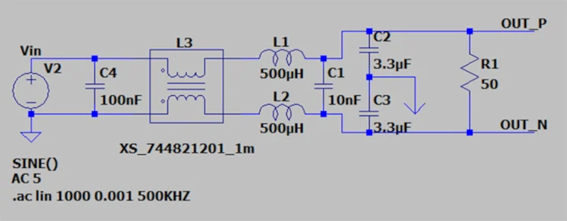
The post shows how to model both types of noise and also covers how to model real-world circuit elements that will more accurately capture the behavior of a real filter. Armed with a good model of noise and some Bode plots, your filter design work will be much easier and robust.
EMC, or electromagnetic compatibility, is crucial for commercial devices. Testing is expensive, so the more you can work out in a simulation, the better. If you need a kick start on using LTSpice, we got you.


Good info on LTspice. One clarification on common mode vs differential mode noise:
Common mode noise current flows in the same direction (common) on the signal conductors and returns on earth ground (not signal ground) or some parasitic path.
Differential mode noise current flows in opposite directions (different) on the signal conductors (ie the signal conductors form a complete circuit), just like the signal does.
So differential noise will likely have current flowing in the same direction as the signal current. In other words, it’s a noise signal superimposed over the signal, as opposed to noise superimposed over ground or similar (which is common mode).
“differential noise having currents that flow in the opposite direction of normal current flow.”
What? I thought differential noise was like, you know, noise that manifests as an actual difference on a differential pair, which looks like your signal, and isn’t removed by the differential signaling process.
What is the “direction of normal current flow”? If you’re simulating noise, you probably have some AC signals happening, and there is no direction.
Right. One benefit of using a differential pair is that it’s inherently less susceptible to differential noise because of the limited loop area and things like that. And it will tolerate some common mode noise (eg a voltage with respect to ground) because the receiver is detecting the signal with a comparator that will mostly ignore the common mode voltage that the signal is rising on top of.
Simulation for the purpose of EMC compliance is valid for first-order effects. But much conducted and radiated emissions will not be seen in a simulation unless you are able to define and model the effects from PCB layout, secondary effects from intra-component reactances, and material effects.
[Ignacio de Mendizábal] said: “For the case of common-mode noise, it can be simulated by adding a voltage source to the return path.”
Um, I don’t think so. Two noise sources would normally not be coherent and therefore not additive. To simulate common mode noise in a SPICE simulation put a single noise voltage source across the circuit input and ground reference the entire circuit to a single ground point through a very high (e.g. 10G) resistance.
By the way, in [Ignacio de Mendizábal’s] post I see references to noise measurements, but none of the voltage sources are actual noise sources, they’re all sinusoids which is fine for CMRR measurements and Bode plots, but you’re not working with noise. Working with an actual noise input can provide some interesting information, like measuring distortion by looking at noise-power-ratios between the passband and stopband of a notch filter.
I thought about that too. But while neither source is an adequate representation of the common mode noise, any imbalance between them will cause something like common mode noise, with return through the ground circuit. So useless for measurement, but technically meets the goal.
But I think you are correct, for simulation of common mode noise it is more realistic to put the source in the ground return.
Also note that chokes can saturate, so if you are trying to filter a high power emitter (like switch mode power supplies), your simulation might not give realistic results.