A presentation this month by the Antique Wireless Museum brought British engineer and inventor John Sargrove (1906-1974) to our attention. If you’ve ever peeked inside old electronics from days gone by, you’ve no doubt seen point-to-point wiring and turret board construction. In the 60s and 70s these techniques eventually made way for printed circuit boards which we still use today. But Mr Sargrove was way ahead of his time, having already invented a process in the 1930s to print circuits, not just boards, onto Bakelite. After being interrupted by the war, he formed a company Electronic Circuit Making Equipment (ECME) and was building broadcast radio receivers on an impressive automatic production line.
Mr. Sargrove’s passion was making radios affordable for everyone. But to achieve this goal, he had to make large advances manufacturing technology. His technique of embedding not only circuit traces, but basic circuit elements like resistors, capacitors, and inductors directly into the substrate foresaw techniques being applied decades later in integrated circuit design. He also developed a compact vacuum tube which could be used in all circuits of a radio, called an “All-stage Valve“. Equally important was his futuristic automatic factory, which significantly reduced the number of factory workers needed to make radios from 1500 to 50. Having completed the radio design, he was also developing a television receiver using the same concepts. Unfortunately, ECME was forced into liquidation when a large order from India was cancelled upon declaration of independence in 1947.
You really must watch the video below. There are many bits and pieces of modern factory automation which we still use today, yet their implementation using 1940s techniques and technology is fascinating. Further reading links after the video. Thanks to [Mark Erdle] for the tip.
- Article in Modern Mechanix, Apr 1948
- Obituary, The Radio and Electronic Engineer Vol 43, No 3
- QSL.net article on Sargrove and Eisler


Is there such a radio survived somewhere?
Is it still operating and can be seen?
Well, it has the disadvantage of having all the wearing parts like potentiometers sprayed on, so it’s not repairable as such.
Scrape it off and reapply.
Yes. The difficulty is “how?”.
Paint brush, silk screen, stencil and sprayer, pad printer, or maybe cut conductive rubber sheet to shape and glue on.
It’s kind of subtle, but clicking on “presentation” in the first sentence will bring up a video with the backstory of Sargrove and the E.C.M.E.
View it here: https://youtu.be/sYfUWuX2dbE
The video linked to “presentation” in the first sentence of this blog post, speculates that only 200 to 500 radios were ever built and there are only a few, maybe 4, known surviving Sargrove radios.
I’ve never seen one, nor any “circuit board” like those. I think it was ahead of its time, and the process needed optimization. Spraying grit? Good grief.
Clearly inspired by the Wallace & Gromit movies.
Or vice versa.
Why didn’t another company buy all the patents etc and keep going with this technology? GE, RCA and the rest happy to see this all go away so they could keep on with their clunky stuff rather than advance the state of the art?
It’s possible, a lot of poor management back then that took a lot of companies down when foreign upstarts worked out how to do it better – “But we’ve always done it this way” or “But this one is made in Britain!” etc.
Sounds very similar to North American automotive manufacturers.
Labor unions as well. There was the so-called “post-war consensus” that favored the nationalisation of industries and attempted to gain full employment as part of the social welfare policy.
The state basically nationalised the weakly performing industries to keep people working despite their lack of productivity. This caused the acceleration of inflation, which eventually lead to the “Winter of Discontent” when all the trade unions started to go on strikes over low pay at once. The labor party basically ran the economy into a wall and Thatcher used that for political advantage.
The Radio, it seems, is a Sargrove A3… https://collection.sciencemuseumgroup.org.uk/objects/co35127/two-valve-radio-receiver-made-on-the-ecme-machine-1947-1948-radio-receiver
https://www.google.com/search?tbm=isch&q=sargrove%20a3&tbs=imgo:1
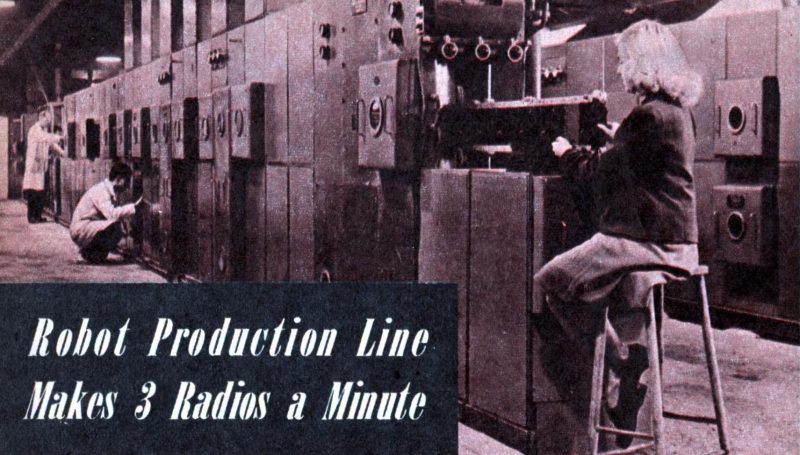
With the amazing amount of automation the complete lack of ergonomics always amazes me.
Not even a cushion on that stool.
Be glad it wasn’t a bed of nails.
I think while looking for how they failed you missed their successes. Access to the production line is at chest height and about 1 arms length deep at most on either side. All the machinery is enclosed and the work area is clean. The walkways are free of obstruction. If a cushion is the worst thing they missed, I think they are doing well. Also cushions wear out and would add another maintenance item to the machine,
Ha, Ha, Ha. 😂
The Radio is a Sargrove A3, in case my other post with image links does not make it through…
How was this radio powered? I did not see a transformer and I thought I heard the words “mains dropping resistor” which sounds both primitive and scary.
You’re right, it was both primitive and scary, but it was common back then in low cost radios. Some radios used resistance line cord instead of a traditional resistor. Cover that cord with a rug and you might burn the house down.
That is a really interesting way of implementing capacitors and coils! Assuming you used a pcb with no internal layers (or were smart about trace placement on the internal layers) can you implement coils like this on modern pcbs? Obviously regular thru hole/smt for the caps, but are coils worth doing as traces separated by the pcb nowadays?
Yes!
Good search terms:
PCB motor
PCB inductor
PCB capacitor calculator
example results:
https://coil32.net/online-calculators/pcb-inductor-calculator.html
https://hackaday.com/2018/05/12/the-current-advances-of-pcb-motors/
https://www.daycounter.com/Calculators/Plate-Capacitor-Calculator.phtml
Coils and transformers etched as part of the normal PCB have been in production (mostly in miniature DC to DC power converter modules) for a number of years. And so-called “thick film” carbon pastes have been silk-screened onto PCB traces to make resistors for a couple of decades. Capacitors, except for very small-valued ones, are not practical because they’re only a single layer of dielectric (as shown in the video). I’m amazed to see that many “modern” techniques borrowed heavily from the ideas of Hargrove – he was certainly far ahead of his time! An example of technology rising to unimagined heights because new engineers are standing on the shoulders of giants!
“It is an automatic manufacturing plant which has the distinction of being the first robot to reproduce it’s own kind”
I’m imagining John Sargrove playing a roll in the childhood of Adrian Bowyer.
I seem to remember a documentary from US military in the 50s, watched on YT several years ago, that explains how “gadgets” are built and integrate a dozen parts on standardised ceramic square chips, right before the silicon integrated circuit took off. I can’t find it anymore on YouTube though. It was interesting because I had not seen electronic ceramic fabrication before…
Though we’re all pretty sure we know what VLSI means now, the categories of MSI and LSI, medium and large scale integration were moving targets throughout the rapid postwar advances up to the 1970s. Therefore are somewhat hard to research when it seems to mean one thing one year and something a bit different the next. There were some quite innovative baked in or potted modules equivalent to chips, that were very compact for the era. The ASICs of their day, they only got used in extremely large production runs or for critical military applications.
I’ve got a fascinating Xeroxed and bound advanced mid 70s *college text “Microelectronic Technology” that seems to be the apex of this kind of tech, dealing with hybrid circuits, thick film circuits, thin film circuits, etc. It seems that it spawned surface mount component tech as a thing that could be used on more stable and electrically superior PCBs as they became available rather than needing ceramic boards. Then the increasing availability of ASIC tech through the 70s probably killed it off for other than high end microwave applications.
(* no ISBN, it seems to be an in house produced tome from an unidentified program, possibly a masters, or potentially a kind of primer briefing document for engineers working at Ferranti or ITT facilities that were in the area. Possibly contains articles and/or academic papers from the industry, rather than original content, no authorship indicated.)
I think I worded that clumsily. In the early years of this tech if was for bigger money, higher production I think, but then later probably mid 60s through 70s became more amenable to medium-higher cost short runs.
Not having anything near a decent scanner setup at the moment I went digging to see if this or similar texts had been digitised. Not this one, but came upon two that touch on some of the techniques in less depth.
First a 1967 article , a review of past and present packaging..
https://www.jhuapl.edu/Content/techdigest/pdf/APL-V07-N02/APL-07-02-Zimmerman.pdf
Next a piece from a Navy Technicians course, hard to date, mentions a milspec that was apparently superseded in 1974. A couple of the photos might be ones used in the xeroxed book, but badly degraded.
http://dl.icdst.org/pdfs/files3/d4178c71c0625e451b1347918f67d56d.pdf
I remember when Panasonic went all in for thick film resistors printed on the board. What a mess as one then another went towards open.
This radio had a really sick volume “pot”, only part of a turn for use. That speaker looks awful too. It looks like they copied the Volksradio in style. The schematic looks like a radio fit for local only use and poorly selective too. Needless to say I always hated line operated (no transformer) radios, as well as ordinary AM radios that needed an external antenna.
That robot on the stool has a nice hairdoo, shame this technology wasn’t more successful.
Any idea why it didn’t catch on?
Sargrove Radios might be long gone, but the company who made the metal spraying equipment are still going strong.
https://www.metallisation.com/applications/metalsprayingofcapacitorends/
(I showed the video to a friend, who recognised an old product of the company he works for)
If any of you want to try this at home…..
Arc spray is interesting, I wonder could a 3D printer be made using it.
printed circuits were used in ww2 by the germans in ther fug direction finding receiver in which silver trackd were sprayed on a ceramic plate to form a printed circuit they fitted ceramic tube capacitors on to this with very short or no leads the first surface mounted capacitors i think the germans gave up with this after the war sargrove system would be too expensive in equipment so failed new ways i dream of wires where are the tracks where are the lines