The inlet and exhaust valve timing of a piston engine plays a large role in engine performance. Many modern automotive engines have some sort of variable valve timing, but the valves are still mechanically coupled together and to the crankshaft. This means that there is always a degree of performance compromise for various operating conditions. [Wesley Kagan] took inspiration from Koenigsegg’s camless Freevalve technology, and converted a Harbour Freight engine to camless technology for individual valve control.
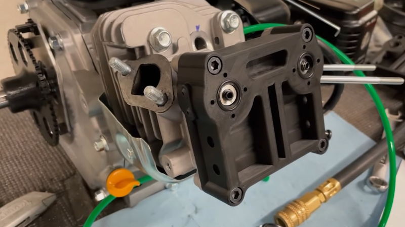
By eliminating the traditional camshaft and giving each valve its actuator, it is possible to tune valve timing for any specific operating condition or even for each cylinder. A cheap single-cylinder engine is a perfect testbed for the garage hacker. [Wesley] removed the rocker arms and pushrods, and replaced the stock rocker cover with a 3D printed rocker cover which contains two small pneumatic pistons that push against the spring-loaded valve stems. These pistons are controlled by high-speed pneumatic solenoid valves. A reference timing signal is still required from the crankshaft, so [Wesley] built a timing system with a 3D printed timing wheel containing a bunch of embedded magnets and being sensed by a stationary Hall effect sensor. An Arduino is used to read the timing wheel position and output the control signals to the solenoid valves. With a rough timing program he was able to get the engine running, although it wouldn’t accelerate.
In the second video after the break, he makes a digital copy of the engine’s existing camshaft. Using two potentiometers in a 3D printed bracket, he measured push rod motion for a complete engine cycle. He still plans to add position sensing for each of the valves, and after a bit more work on the single-cylinder motor he plans to convert a full-size car, which we are looking forward to.
People have been tinkering with cars in their garage for as long as cars have existed. [Lewin Day] has been doing a series on how to get into tinkering with cars yourself. With all the electronics in modern automobiles, messing around with their software has become a growing part of this age-old pastime.


I hear a lot of those HF engines are copied Honda designs from the 1970s… which is when Honda were playing around with lean burn and stratified charge… which might be an avenue to explore on them.
Looks a lot to me like one of millions of Honda GX clones which are Honda’s industrial engines, fitted to everything (generators, compressors, mowers, go-karts and likely a few quads), I don’t think there’s any revolutionary quirks to them other than being an incredibly reliable and robust unit.
Honda still make them, must’ve made millions by now:
https://engines.honda.com/models/model-detail/mid-gx
Also to the person writing the article – it’s HARBOR. There’s no “U” in it. It’s not even a silly European/American thing. It’s literally the company’s name. FFS get it together guys.
LMAO, I was going to ask “Where can I get these wonderful Harbour Freight engines at? Maybe they stock them at Tyres Plus”
They are copies of Honda’s current line-up of engines which are found a lot on lawn care equipment, mowers, and construction equipment. Honda never patented anything except the recoil housing so you’ll notice that is different on all the copycat engines, but pretty much the rest is the same (some air cleaner differences.) You can order Honda parts that will fit right on the HF engines. In fact when I attended an official Honda repair school, they originally told us how poor of quality the copycat engines were. The last one I attended they said, “We can find nothing wrong with the copycat engines so our advice to you is just sell people the parts they need.” That came from an official Honda dealer that sells and repairs Honda engines.
Nice, I first heard that probably 15 years back, so they might have had the older designs then. I have had that impression over the last decade though that they’ve gone from “temporary replacement” motors that will do you a couple of months to as reliable as the originals.
I’m actually pondering using one as a marine engine, mid 20th century there were tons of users and designs around for air cooled inboard motors, 2-15 HP, but those motors got rarer, as did unfortunately the things like propeller, skeg bearing and shaft log assemblies suited to them. In the 50s, these were generic parts, but early in the century they seemed to have been homebrew or fettled by a marine mechanic. I am still digging old sources trying to find info before the switchover. There’s nothing rocket science about them really, it’s just I’d rather have something that fits and works okay, using the rules of thumb previously delineated rather than a “development program”. They still build boats like this out in Asia, India etc, I don’t know if all the parts are locally “blacksmithed” or whether there’s still some manufacturing and it’s a language barrier thing keeping me from finding where. Okay I CAN phone a north american marine dealer and have “yacht parts” ordered cast in platinum-iridium-naval bronze, buffed to a high shine and packed in a velvet lined oak case, because yachts still use inboards, and everyone with a “yacht” obviously has $10,000 to spare at any given moment, but I’m tryna find the ones they used to use for fishing and utility boats. Suffice it to say that lost PLA casting is looking like an attractive option. Heh, it’s kind of annoying actually, you get references like “pack the stuffing gland with pitch and oakum in the usual way” and I can’t find a reference to what actually was the usual way, and modern marine sources are like “Ah yes, you need the teflonic vitonium fibrotastic NASA engineered no-drip hydrophobic shaft gland available in a range of sizes from too big to absolutely massive starting at only $700.” (I also have the suspicion that parts of that type are nothing more complicated than is a $5 viton camshaft seal from the auto part dealer.)
Anyhoo, in my estimation, motors of this type now are far more reliable, economical and durable than the motors previously used for small inboards hence maybe that’s why outboards became more popular, however the outboard game has got a bit monopolistic, so prices are not very favorable to the average Joe any more. These would be, if I could figure out how to get the rest of the install down to under $500.
You could build a Thai long tail boat. https://en.wikipedia.org/wiki/Long-tail_boat
Here’s my longtail: https://arduinoinfo.mywikis.net/wiki/Boat_Building_Jon_Boat
The HF engines are so good these days that they’ve replaced the real Honda engines for high performance racing karts. Builders get astonishing amounts of power out of them, and some have gone as far as putting turbochargers on them.
Isn’t there something about these sort of valves needing more energy to actuate, or maybe it was the switching speed that was usually limited and thus made that part too expensive for mass manufacturing?
Maybe solenoids have caught up a bit now, but it was the case 20 years ago that they were thought too slow and too power hungry, given that car alternators are typically inefficient, so your 1HP lost swinging the knobbly stick became 2HP more resistance at the alternator to do the same job.
If you were a brand new motor company, greenfield site, cleansheet design of everything, it might look today that the options are more evenly balanced. But if you’ve already got all the machinery and staff trained to design and mass produce camshafts, it probably needs to show huge benefits before you’ll change. Particularly since most of the benefits can be replicated by oil pressure control of the lifters and phasing of the cam, requiring much smaller solenoids.
Or one can look at it like this.
One looses a bit of extra power compared to a mechanical linkage, but the advantages of finer valve timings offers more overall performance.
Ie, you might loos 1 more HP in the process of gaining 1-2% more power from the engine. And for a a 200+ HP engine, that outweighs the additional power demands. (Except, in Koenigsegg’s case, their engines are a lot higher power than 200 HP, so 1% is a handful of HP, let alone 2%. Though, I think they gain more than that to be fair.)
But for non race applications, the advantages can be less useful. Though, overall fuel efficiency can still increase, so even then it can be a worth while change.
Though yes, technology has moved forth and more efficient mechanisms do exist.
Great!
But… Salad of valves and pistons in sight if the Arduino fails…
Projects like this definitely need a damn good watchdog and “fail safe” (valves stay closed) modes but for a bit of R&D with a cheap lawnmower engine it’s not the end of the world – definitely want to have it proven reliable before bolting it to an engine you care about though!
Only if it’s an interference engine, which I doubt these cheap ones are. Worse that can happen is probably a violent backfire.
Worst that can happen, not worse
By the way, all the vehicles I’ve worked on with hall effect sensors for timing purposes don’t seem to need to use magnets, just toothed steel parts. I guess the disturbance in residual magnetism from the air gaps are enough to detect. Or they kind of focus whatever field lines are ambient. Though I guess if you’ve gotta add things to your lump of plastic, the magnets make sure of it. I’d probably have cut it out of plate with a printed template though.
There is a magnet. Its behind the sensor, not on the tooths.
When a teeth comes close to the sensor it “steers” the dield of the magnet behind the sensor to pass through the sensor more -> observable change on the sensors output.
It is called variable reluctance sensing. Automotive designs count the teeth on the ring gear I think. There is typically one missing tooth for “indexing”
VR is different from Hall effect. Both are used extensively in cars. The primary differences in usage are that VR is a two-wire sensor, in which both wires are part of a differential signal with a sine wave profile that requires a zero crossing detector to process, whereas Hall effect sensors have three wires, two for power and a single-ended square wave output making them much easier to interface. Ratiometric HE sensors exist, but aren’t typically used for gear sensing since the internal signal amps for both are basically identical to produce (one a diff amp, the other a comparator).
And 2wire hall sensors exist tho these are seldom(never?) Used for engine sensors and only found in abs systems for detecting wheel speed. Visually they can be distinguished from vr sensors as vr sensors are always much bigger.
When pneumatic valve springs were first used in racing, in Formula 1 (has that tech been banned from F1), the valves had light coil springs to keep them seated. To maintain pressure a gas bottle (IIRC it was nitrogen) was put in, with enough gas to compensate for leakage during the course of a race. The valves were actuated normally by the overhead camshafts.
The idea was to remove the lag of metal springs to eliminate valve float (typically partially prevented with one coil spring inside another, with different numbers of turns) because a gas doesn’t have the inertia that can cause a metal spring to continue to compress after the compressing force (the camshaft lobe) is removed.
A small air compressor and reservoir tank, with an air conditioner clutch to engage as needed, would work fine for street use to keep pneumatic valves working. In other words, modify the smallest automotive AC compressor there is for the job.
Rather than using solenoids, use direct motor driven actuators that are easy to backdrive. Opening the vale is ‘simple’, pulse the right amount of electricity to the motor for the right length of time, at the right time, to get the desired valve opening. To hold position, use PWM to rapidly pulse it, and use the mechanical inertia of the moving parts as an advantage instead of a problem.
With controlled valves, the intake could start out gradually opening as the piston starts to move down, then snap to full open. Whenever you want the compression stroke to begin, shut the power off so the gas spring can snap the valve closed faster than a cam lobe’s gradual letoff.
For exhaust the valve could snap to full open right as the piston starts to come up, then as the piston approaches the valve, let off gradually so the valve closes right at TDC.
With such a system any amount of valve overlap could be used for best exhaust scavenging, emissions control, switching on the fly between Otto and Atkinson cycle operation etc.
I’m not sure the slamming them closed thing is gonna be good for the valve faces or seats, because there’s no reason at the cam end not to let them just drop. The spring however can bounce, I think I’ve heard that about having the cam cut too sharp a drop off, the valve slams and bounces several times on the spring.
racing motors only have to survive 1 race.
Not in MotoGP where the number of engines you’re allowed to use per season is controlled. Ask Yamaha.
True… I keep reminding the ppl that tell me that racing oil is best for my engine of that.
Generally a lot to sort out in terms of used or banned from racing, when you are thinking of trying it out, was it too good, was it too bad, was it highly expendable. Then the old “if it did anything they’d do it at the factory” yeahno, it might be 25c more than the way they did it, it might be high labor cost, it might make the motor all snarly and scare the buyers so marketing kiboshed it.
So true – racing engines have lifetimes measured in hours, I read an article that said some top-fuel drag engines may do fewer than 1000 complete rotations from start to finish and total rebuild (or catastrophic failure).
F1 teams get three engines per season. They changed that rule just a few years ago.
Have a look at the desmodromic valves, largely used by Ducati. Make it a push-pull system and have a square camshaft for all that matters, the valve will always follow!
https://en.wikipedia.org/wiki/Desmodromic_valve
Have you ever owned one and needed to bring it in for the $$ service charge to service that valve train properly? Pass.
Have you ever owned one Ducati? I own a Ducati 996 and do the maintenance myself. Yes, valve adjustment is slightly more complex than a normal engine. But nothing more complex or expensive (if you go to a mechanic) than the maintenance of such a racing engine. Do you want to put the deep pleasure of driving it though?
Ferrari did test solenoid actuated valves for their V-10 back in the early 2000. However the Honda GX31 test unit was done by the University of South Carolina article here http://www.me.sc.edu/research/AARG/images/AARG/Camless%20Page.htm
Patent for a solenoid actuated valve was registered by Mr. Sturman back in 1994 https://patents.google.com/patent/US6575126B2/en
When I was in Engineering school, we built a Nitrogen driven unit similar to the F-1 approach. The problem was recharging the Nitrogen bottle after x number of runs. We did look at a hydraulic driven unit but FIAT had patented a similar design years ago.
Brainfart.
Use oil instead of air since a liquid can’t be compressed, thus eliminating “slop” from actuation, and base the solenoid valve on parts of the base design of a modern commonrail diesel injector.
They basically only need a small pulse to “unseat”, then the high pressure of the diesel by the rail pump forces it open and keeps it open.
And it is then closed by reversing the voltage of the injector valve, which with some mechanical wizardry makes the high diesel pressure close the injector.
Then try to start it with a cold engine -> valves won’t open
Direct acting piezo injectors sort of work as you describe, pulse one way for on, other way for off. The piezo stack directly actuates the high pressure iirc. There are also indirect piezo injectors, and indirect solenoid injectors (energised =open) given these injectors can operate comfortably 3-4 times per combustion event using them to operate a valve , which is much slower, seems well within the grasp of the tech.
Don’t use non-synthetic 20w50 shitbox oil, but rather something like fully synthetic 0w20.
Thats like water when hot, and like cooking oil when cold.
Or even better, separate oil loop with dedicated low viscosity hydraulic fluid.
Also forgot, most commonrails can start even when it’s cold AF, as long at the combustion chamber itself is hot thanks to glowplugs, so it’s all about pressure.
Seriously, go but some diesel in a jug in a deep freezer and take it out after a few hours to slosh it around.
It ain’t high viscosity I tell you.
Um, you are replacing a spring and a camshaft, the ‘springiness’ of the air is a feature
That only means actuation latency, unless you like Apple’s definition of features.
Which for something like cam timing in a possible high RPM application is a big no-no.
There’s a reason they go for insanely stiff springs, or desmodromic valves, and that’s to eliminate as much slack and slop as possible, which could lead to less tight valve timing or even valve float.
Which my hunch working with pneumatic systems tells me would happen with this.
This differs quite a lot from the nordic system this is based on, in that the camshaft is eliminated, but NOT the springs. This system floats just as much as a standard one does. The difference is in the arbitrary compression profiles that can be used.
Harbor* Freight. It’s a proper name of a US based company and thus should not be subjected to differential worldwide spelling.
Some of the greatest inventions and innovations started with someone tinkering like this in a garage, so I hope he stays with it to fruition.
I watched most of the video and I couldn’t help but think it deserves the title “How to make something unnecessarily complex”
It is an interesting experiment to see if it could be done, and opens a possibility for infinitely variable valve timing. However, at what point does the added complexity outweigh the practical benefits? Sure, there could be fuel efficiency and/or power gains to be had, but now you literally do need a degree in computer science just to work on a lawnmower engine!
You could learn enough electronics and programming in WAY less time than you could learn how to do a mediocre job grinding a cam. Not to mention the massively reduced tooling costs, or the cost of making a change if your first one doesn’t perform as desired.
Modern cars are already full of sensors and electronics, and can indeed be more difficult to service without knowledge and specialized equipment/software. This electronic valve actuation is just taking it one step further.
On the plus side, there is no longer any need for the whole timing belt/chain mechanism. On some cars replacing these parts (every 100-120k km) is quite an expensive service, which can now be eliminated.
Without a camshaft, the head can likely be made more compact. The system can be more enclosed – less oil seals that one day start leaking.
If both control electronics and valve actuators are perfected, I think this concept can achieve higher overall reliability/durability over a traditional timing mechanism.
Although manufacturers should probably invest their R&D into electric cars.