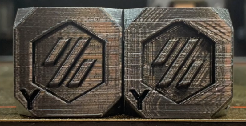
It seems as though we still can’t hit the ceiling on better control schemes for 3D Printers. Input Shaping is the latest technique to land on our radar, a form of resonance compensation that all but eliminates the ghosting (aka: vertical ringing) artifacts we see on the walls of printed parts. While the technique has been around for decades, only recently did [Dmitry Butyugin] both apply it to 3D printer control and merge their hard work into the open source firmware package Klipper. Once tuned, the results are simply astonishing–especially since this scheme can augment the print quality of even the most budget printer.
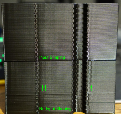
Input Shaping is a feed-forward controls technique for cancelling the mechanical vibrations that create ghosting. The idea is that, if we wanted to move the machine from point to point, we send it two impulses. The first impulse kicks the machine into moving and the second impulse follows up at a precise time to cancel the vibrations we would see when the machine comes to a stop. Albeit, moving any machine by sending it two impulses is pretty crude, so we take these impulses, adjust their amplitudes so that they sum to 1, and convolve them with a control input signal that we’d actually like to send it. The result is that the resonance cancellation part of the signal seamlessly “mixes” into the control input signal, and the machine moves from point to point with significantly less vibration at the end of the travel move. For more info on the maths behind this process, have a look at the first four pages of this paper from [Singh and Singhose].
The only hiccup is that you need to do some up-front system characterization of your 3D Printer running Klipper before you can take advantage of this technique. Thankfully the Klipper update comes with a set of step-by-step instructions for characterizing your machine up-front. After a couple test prints to measure the periodicity of your ringing, you can simply apply your measurement results to your config file, and you’re set.
Input Shaping is a prime example of “just wrap a computer around it!“–fixing hardware by characterizing and cancelling unwanted behaviors with software. If you’re hungry for more clever, characterized hardware control schemes, look no further than this Anti-Cogging algorithm for BLDC Motors. And for a video walkthrough of the Klipper implementation, have a look at [eddietheengineer]’s breakdown after the break.
Does your 3D Printer run Klipper? We’d love to see some of your Input Shaping results in the comments.


This is old hat in the CNC world. Professional level machines have had high feed lookahead options for decades.
“While the technique has been around for decades, only recently did [Dmitry Butyugin] both apply it to 3D printer control and merge their hard work into the open source firmware package Klipper.”
Dont think they are the same. This one is for basically trying to compensate for vibrations due to flimsy frame. The one you refer to is for improving machining time i believe.
No, it actually slows down cutting time a bit, but significantly improves accuracy and surface finish. No machine is perfectly ridgid.
3D printers also have had acceleration lookahead to slow down ahead of corners for a long time now. Smoothieware has 32 segments lookahead if I recall correctly.
But this is different in that it modifies the velocity curve based on machine characteristics. I bet that also exists in CNC world, because at least PID controllers for the servo drives are usually tuned for the weight of the machine.
https://www.mmsonline.com/articles/a-closer-look-at-look-ahead
There’s a distinction between knowing a technique and actually implementing it: only the latter gives actually better parts.
you’re so smart!
can you point us to the code that you’ve developed to implement this for 3D printers?
because if you’re only here to criticize the actual work of others with your “I already knew this but never bothered to invest my skills to helping others”, then you should just keep your trap shut.
You are just as bad. Full stop.
Hahahaha legit the horror.
Whats wrong with your printer?
I disagree with the assessment that either of them are bad.
Im pretty sure that makes you worst of all
So now let’s implement it in GRBL so even the low-end, amateur machines have it. Nothing like reducing a $30K machine down to $200 and some free software.
Or just install Klipper on your CNC. Klipper is free too!
Lookahead is not resonance shaping, name one machine using a resonance control algorithm so I can look into it, very interested!
This is brilliant! Compensating for resonance(vibration) using software is absolutely brilliant!
In the duet forums, there’s a thread with a person implimenting a spring-damper filter you can run on your output g-code, the results were really impressive how it even reduces ghosting on top of s-curve controls.
In the future, I hope everything that moves via electricity has this kind of thing built in, and it becomes standard practice to include accelerometers and software control over as many parameters as possible.
In fact, we should have a whole research institute entirely dedicated to seeing how much hardware and mechanical gear can be replaced, or have it’s lifetime extended, through pure software controls.
This is exactly the kind of innovation that’s really moving the world forward with basically no cost or downside. You can’t always do it, but when you can, it’s amazing. Well done!
An acquaintance was a maintenance mechanic in a big (food) production/packaging facility. He always said the most reliable machines were the ancient cast iron pure mechanical behemoths. The modern electronic controls machines were the ones breaking down the most, in constant need of servicing and repairs. YMMV.
Yeah, it seems like the sort of thing that would allow manufacturers to cut even more corners than they already do.
Yep. I know shops still cranking out parts on the old war era Brown and Sharp cam operated screw machines. 60+ years old and still going strong. The hardest part is finding people who know how to work with them.
Personally, I prefer a machine with predictable mechanical repeatability and tolerances. Lead shot filled cast-iron with gibs for the long-term win… ;-)
In a modern factory, tighter process control means tweaking the machine as it ages or material properties vary. A classic cam or gearbox based mechanism simply wears out in a predictable manner, and usually fails catastrophically unless regularly inspected. High-power servo control of rollers for example, are compensating for dozens of changes in the mechanism over time. The key concept here was if it was designed correctly, and a system has well defined universal standard control components with open code access. Factory downtime can be more expensive than paying a fellow to sit there with a “finger on an airline leak” just to keep the machines running.
It has been my experience that modern firms simply bring up a parallel production line somewhere in the middle of a primary lines bath-tub curve, and simply scrap the problematic line when the maintenance issues pose a significant cost. There are several reasons this often makes sense, but if you ever try to source a chip or PLC from 10 years ago the decision becomes easier to understand.
When I built my first full metal Prusa i3 style kit with a Bowden style extruder, the limits of belt drive systems were not the issue (added a guide to reduce it flapping around). Rather, the constraining factor was how fast one could feed the ABS filament through the hot end reliably without jamming. Typically, I ran the nozzles hotter than most setups, and would simply back off the print speeds by 30% well below where the filament is known to jam (marlin firmware would not glitch 30h into a print, so is still my favored choice).
I learned a lot owning an early model Mendel printer, and had a clear idea of the next FFF reprap design I wanted. Specifically, choosing bearing parts that would last, thread-lock adhesive on every mated-surface/thread, and aluminum brackets that could survive in a 80’C chamber without issue. 5 years later and dozens of kg spools fed, the only maintenance I have needed to do was regularly oil the surfaces before each use, tension the belts, and clean the nozzle once a year.
I may be wrong, but the amount of wear on the quiet plastic-roller style machines looks like a problem area. Maybe people that own one of these can offer some insight into how long they typically last. =)
selection bias rules everything around us.
Remember the selection effect! The cast-iron behemoths that broke aren’t on the assembly line anymore.
No, they have mostly been sold to China, where they now out-compete us with them, having stuck them back together with bailing wire.
Yah but in the home shop it’s a lot easier to cast Epoxy Granite than Iron!
“Input Shaping is a prime example of ‘just wrap a computer around it!’–fixing hardware by characterizing and cancelling unwanted behaviors with software.”
I prefer the phrasing, “compensating for hardware…”. The hardware is what it is, and certainly hasn’t been fixed. That is always true, whether your machine is made of granite or wet noodles. Control engineering can always improve a machine’s capabilities.
I kind of want this for a lot of things on my printer. For instance, sometimes when watching the first layer being put down, a lot of the problem points often seem to be places where things are going well until the system switches from “carefully laying down filament” to “zooming somewhere else”, or vice versa. Likewise, it feels like corners can be taken too swiftly. I know, I know, this is because my printer sucks and/or my maintenance sucks and/or my filament sucks, but it feels like this kind of comprehension of the physical system’s attributes could make things more robust.
Change your acceleration parameters or even better get to know your linear advance values. Those corners can be fine tuned pretty tight
Would an accelerometer be fast enough to be able to record the ringing caused by the movements of the hotend? If so, it should be possible to slap an accelerometer there and for the firmware to go through a series of movements to find when and how to compensate automatically without requiring manual tuning from the user. Obviously, the firmware would have to support this, so it can’t just be added with some modifications to the slicer, but it could be a neat feature for some printer to integrate.
You didn’t read the docs? ;-)
https://www.klipper3d.org/Measuring_Resonances.html
Klipper supports an accelerometer now for initial tuning. You run some moves and it graphs the resonant frequencies for each axis.
Yes! Dmitri’s code includes a calibration routine that estimates the best parameters via an accelerometer 😄
Seems like this could also be something to monitor throughout the print, rather than just an initial calibration. The firmware knows where it told the steppers to move, and use the accelerometer for feedback that the print head actually did what was expected and to fine tune in realtime. I am also sure that the resonance of the print head changes depending on where it is on each of the axis.
Prusa’s MK3 can detect layer-shifts, skipped steps and unexpected movement of the extruder via the Trinamic-drivers even without an accelerometer. Still, it doesn’t seem like it’s precise/fast enough for this kind of resonance-tuning, so there’d still be something to gain from one.
I’ve not finished my MK3s build, but to put some real world numbers on it, my ender 3v2 runs Marlin firmware at 500mm/s/s acceleration for best quality and 800mm/s/s for when I don;t mind a bit of ringing. Using Klipper’s input shaper i’m running at 4000mm/s/s with great print quality and no ringing.
Whilst my hotend can do 15mm3/s of PLA (that’s about 150mm/s at 0.2layers for me) which isn’t much more than an E3Dv6, upping the acceleration so much means I’m achieving that flow on much smaller parts, not just printing big boxes.
You mean closed loop stepper / driver ?
Rigidity and vibrations are two important factors when it comes to machines being accurate.
Though, canceling out vibrations and resonance can at times become a bit of a headache in itself, since not only is it effected by the machine’s movements, but at times where in its movements it is, not to mention how the part one works on can add weight to the machine and alter resonance yet more…
Having software to counteract known resonances in the machine is going to help a bit with increasing accuracy. (Or reduce print time with the same accuracy, if the print head can squeeze out filament fast enough.)
But obviously there is other properties of resonances that would need more active compensation, ie, a pre calculated machine model isn’t going to be sufficient. This is though more applicable to CNC machines working with parts with more heft to them, and larger cutting forces. Especially applicable to machines where the work piece itself is getting flung around at 4+G as if it weighs like a feather….
But having compensation for the machine swinging/resonating is better than not having it. Since then one can get more accurate parts from the machine.
Linear advance, or adjusting nozzle pressure with ‘look ahead’, compensates for the springy nature of Bowden tube feeds.
Print the test pattern, pick out the one that suits your machine.
It’s like we are teaching our machines how to have ‘reflexes’.
Pressure advance is only for extrusion.
Resonance compensation is for the movement of the axes.
Biggest thing I have seen this for on big cnc machines, is to make the bearings on slides last much longer by not being hammered at stop points. Slow the head down before stopping. Inertia is an ugly thing at that point.
This is bandaid for an improperly setup or poorly designed printer. I guess it’s good it exists but should be a last resort.
Interesting to see this in 3d printers when weve been using convolvers in audio for years now with FIR filters to digitally correct for room acoustics. Although I’d say correcting for a room is much more involved than this. In theory, this could be taken to the nth level to remove all artifacts, except those introduced by the process itself, into the print.
Here is an example project but there are others – https://www.diyaudio.com/forums/pc-based/349818-camilladsp-cross-platform-iir-fir-engine-crossovers-correction-etc.html