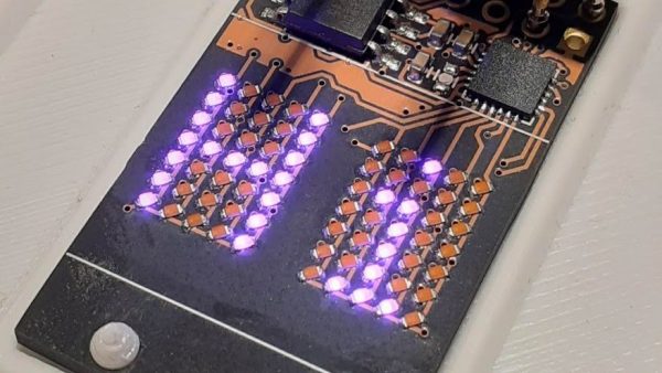
Few things excite a Hackaday staff member more than a glowing LED, so it should be no surprise that combining them together into a matrix really gets us going. Make that matrix tiny, addressable, and chainable and you know it’ll be a hit at the virtual water cooler. We’ve seen [tinyledmatrix]’s work before but he’s back with the COPXIE, a pair of tiny addressable displays on one PCBA.
The sample boards seen at top are a particularly eye catching combination of OSH Park After Dark PCB and mysterious purple SMT LEDs that really explain the entire premise. Each PCBA holds two groups of discrete LEDs each arranged into a 5×7 display. There’s enough density here for a full Latin character set and simple icons and graphics, so there should be enough flexibility for all the NTP-synced desk clocks and train timetables a temporally obsessed hacker could want.
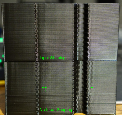
It seems as though we still can’t hit the ceiling on better control schemes for 3D Printers. Input Shaping is the latest technique to land on our radar, a form of resonance compensation that all but eliminates the ghosting (aka: vertical ringing) artifacts we see on the walls of printed parts. While the technique has been around for decades, only recently did [Dmitry Butyugin] both apply it to 3D printer control and merge their hard work into the open source firmware package Klipper. Once tuned, the results are simply astonishing–especially since this scheme can augment the print quality of even the most budget printer.
A Split A/B Test with and without Klipper’s Input Shaping feature courtesy of [@LukesLaboratory]Assuming your 3D printer isn’t infinitely stiff, when your nozzle moves from point to point or changes direction, it vibrates in response to having its speed altered. The result is that the nozzle wobbles along the ideal path it’s trying to track. The result is ghosting, an aesthetic blemish that looks like vertical waves on the sides of your printed part.
Input Shaping is a feed-forward controls technique for cancelling the mechanical vibrations that create ghosting. The idea is that, if we wanted to move the machine from point to point, we send it two impulses. The first impulse kicks the machine into moving and the second impulse follows up at a precise time to cancel the vibrations we would see when the machine comes to a stop. Albeit, moving any machine by sending it two impulses is pretty crude, so we take these impulses, adjust their amplitudes so that they sum to 1, and convolve them with a control input signal that we’d actually like to send it. The result is that the resonance cancellation part of the signal seamlessly “mixes” into the control input signal, and the machine moves from point to point with significantly less vibration at the end of the travel move. For more info on the maths behind this process, have a look at the first four pages of this paper from [Singh and Singhose].
The only hiccup is that you need to do some up-front system characterization of your 3D Printer running Klipper before you can take advantage of this technique. Thankfully the Klipper update comes with a set of step-by-step instructions for characterizing your machine up-front. After a couple test prints to measure the periodicity of your ringing, you can simply apply your measurement results to your config file, and you’re set.
Input Shaping is a prime example of “just wrap a computer around it!“–fixing hardware by characterizing and cancelling unwanted behaviors with software. If you’re hungry for more clever, characterized hardware control schemes, look no further than this Anti-Cogging algorithm for BLDC Motors. And for a video walkthrough of the Klipper implementation, have a look at [eddietheengineer]’s breakdown after the break.
Does your 3D Printer run Klipper? We’d love to see some of your Input Shaping results in the comments.
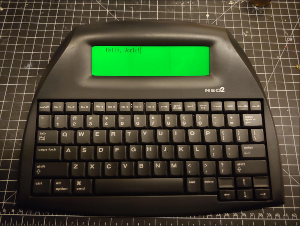
The AlphaSmart NEO and NEO2 are great little word processors for distraction-free writing anywhere you want to go, but they lack the backlight of the later Dana model. Well, [starboyk] has done what many thought impossible and added a backlight to a NEO2. Experience gained from a ton of console mods and repairs led to the question of whether the NEO2’s LCD is similar to a Game Boy’s.
[starboyk] started with a fresh NEO2 from ebay, then swapped out the reflective polarizer for a translucent polarizer and added a trio of LED backlights meant for the original Game Boy across the back of the screen. The best part is that the backlight has its own power switch and a brightness control pot. It sounds easy enough, but this mod is not for the faint of heart as it sounds like a really tight fit in the end. Apparently we only need 500 orders to get a custom backlight manufactured, but barring that does anyone know of a backlight that’s 157mm x 44mm?
You can always stick with the mod where you power the USB-A port and use a USB reading light like I did with my NEO.
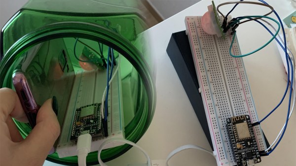
While there are loads of impressive and complex projects here on Hackaday, sometimes it’s the simple ones that really speak to us. In this case we were presented with [Isabell Park]’s easy-to-follow instructable on how to build an anti-procrastination device.
On the hardware side there are no surprises, it consists of a PIR sensor connected to a NodeMCU microcontroller. It checks for a signal from the sensor, and if it’s triggered, it sends a command through the Adafruit IO libraries to IFTTT. On its own it could make for a decent movement alarm, but the part that makes the project interesting is how it’s applied to become a device to help with procrastination instead.
First, you put your phone in a jar along with the electronics and close it. Then, with everything configured, the circuit is powered on and stays vigilant for any movement inside the jar. Should you try to take your phone out of it for a quick social media break (which, if you’re like us, can turn into a few hours), IFTTT will be alerted and run through whatever script you have in place. In [Isabell]’s case, she suggests sending an SMS to a trusted contact to keep you in check.
[Teaching Tech] has been interested in adding a tool changer to his 3D printer. E3D offers a system that allows you to switch print heads or even change out a hot end for a laser or a (probably) light-duty CNC head. The price of the entire device, though, is about $2,500, which put him off. But now he’s excited about a product from PrinterMods called XChange. This is a kit that will allow rapid tool changes on many existing printers and costs quite a bit less. Preorder on KickStarter is about $150, but that probably won’t be the final price.
Not all printers are compatible. It appears the unit attaches to printers that have linear rails and there is an adapter for printers that have V rollers in extrusions. Supposedly, there is an adapter in the works for printers that use rods and bearings.
Circuit simulations are great because you can experiment with circuits and make changes with almost no effort. In Circuit VR, we look at circuits using a simulator to do experiments without having to heat up a soldering iron or turn on a bench supply. This time, we are going to take a bite of a big topic: op amps.
The op amp — short for operational amplifier — is a packaged differential amplifier. The ideal op amp — which we can’t get — has infinite gain and infinite input impedance. While we can’t get that in real life, modern devices are good enough that we can pretend like it is true most of the time.
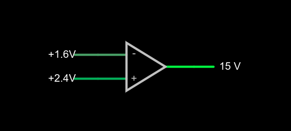
a very simple op amp circuit with some detail omitted
If you open this circuit in the Falstad simulator, you’ll see two sliders to the right where you can tweak the input voltage. If you make the voltages the same, the output will be zero volts. You might think that a difference amplifier would take inputs of 1.6V and 2.4V and either produce 0.8V or -0.8V, but that’s not true. Try it. Depending on which input you set to 2.4V, you’ll get either 15V or -15V on the output. That’s the infinite gain. Any positive or negative output voltage will quickly “hit the rail” or the supply voltage which, in this case, is +/-15V.
Practical Concerns
The biggest omitted detail in the schematic symbol above is that there’s no power supply here, but you can guess that it is +/- 15V. Op amps usually have two supplies, a positive and a negative and while they don’t have to be the same magnitude, they often are. Some op amps are specifically made to work with a single-ended supply so their negative supply can connect to ground. Of course, that presupposes that you don’t need a negative voltage output.
The amount of time it takes the output to switch is the slew rate and you’ll usually find this number on the device datasheet. Obviously, for high-speed applications, a fast slew rate is important, particularly if you want to use the circuit as a comparator as we are here.
Other practical problems arise because the op amp isn’t really perfect. A real op amp would not hit the 15V rail exactly. It will get close depending on how much current you draw from the output. The higher the current, the further away from the rails you get. Op amps will also have some offset that will prevent it from hitting zero when the inputs are equal, although on modern devices that can be very low. Some older devices or those used in high-precision designs will have a terminal to allow you to trim the zero point exactly using an external resistor.
Op Amps Can Provide Steady Voltage Under Variable Load
Rather than dig through a lot of math, you can deal with nearly all op amp circuits if you remember two simple rules:
The inputs of the op amp don’t connect to anything internally.
The output mysteriously will do what it can to make the inputs equal, as far as it is physically possible.
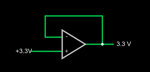
1x amplifier
That second rule will make more sense in a minute, but we already see it in action. Set the simulator so the – input (the inverting input) is at 0V and the noninverting input (+) is at 4V. The output should be 15V. The output is trying to make the inverting input match the noninverting one, but it can’t because there is no connection. The output would like to provide an infinite amount of voltage, but it can only go up to the rail which is 15V.
We can exploit this to make a pretty good x1 amplifier by simply shorting the output to the – terminal. Remember, our rules say the input terminals appear to not connect to anything, so it can’t hurt. Now the amplifier will output whatever voltage we put into it:
You might wonder why this would be interesting. Well, we will learn how to increase the gain, but you actually see this circuit often enough because the input impedance is very high (infinite in theory, but not practice). And the output impedance is very low which means you can draw more current without disturbing the output voltage much.
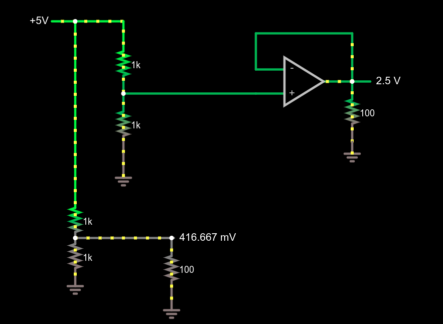
Comparing voltage divider performance with and without a 1x amplifier
This circuit demonstrates the power of a 1x amplifier. Both voltage dividers produce 2.5V with no load. However, with a 100 ohm load at the output, the voltage divider can only provide around 400mV. You’d have to account for the loading in the voltage divider design and if the load was variable, it wouldn’t be possible to pick a single resistor that worked in all cases. However, the top divider feeds the high impedance input of the op amp which then provides a “stiff” 2.5V to whatever load you provide. As an example, try changing the load resistors from 100 ohms to different values. The bottom load voltage will swing wildly, but the top one will stay at 2.5V.
Don’t forget there are practical limits that won’t hold up in real life. For example, you could set the load resistance to 0.1 ohms. The simulator will dutifully show the op amp sourcing 25A of current through the load. Your garden-variety op amp won’t be able to do that, nor are you likely to have the power supply to support it if it did.
What’s Being Amplified?
This is an amplifier even though the voltage stayed the same. You are amplifying current and, thus, power. Disconnect the bottom voltage divider (just delete the long wire) and you’ll see that the 5V supply is providing 12.5 mW of power. The output power is 62.5 mW and, of course, varies with the load resistor.
Notice how this circuit fits the second rule, though. When the input changes, the op amp makes its output equal because that’s what makes the + and – terminals stay at the same voltage.
Of course, we usually want a higher voltage when we amplify. We can do that by building a voltage divider in the feedback loop. If we put a 1:2 voltage divider in the loop, the output will have to double to match the input and, as long as that’s physically possible, that’s what it will do. Obviously, if you put in 12V it won’t be able to produce 24V on a 15V supply, so be reasonable.
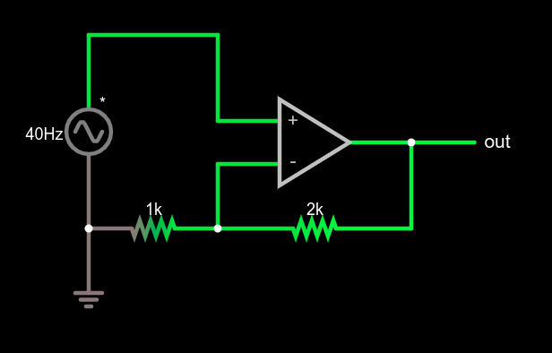
Non-inverting amplifier example
This type of configuration is called a non-inverting amplifier because, unlike an inverting amplifier, an increase in the input voltage causes an increase in the output voltage and a decrease in input causes the output to follow.
Note that the feedback voltage divider isn’t drawn like a divider, but that’s just moving symbols on paper. It is still a voltage divider just like in the earlier example. Can you figure the voltage gain of the stage? The voltage divider ratio is 1:3 and, sure enough, a 5V peak on input turns into a 15V peak on the output, so the gain is 3. Try changing the divider to different ratios.
What’s Next?
While it isn’t mathematically rigorous, thinking of the op amp as a machine that makes its inputs equal is surprisingly effective. It certainly made the analysis of these simple circuits, the comparator, the buffer amplifier, and a general non-inverting amplifier simple.
There are, of course, many other types of amplifiers, as well as other reasons to use op amps such as oscillators, filters, and other even more exotic circuits. We’ll talk about some of them next time and the idea of a virtual ground, which is another helpful analysis rule of thumb.
Hackaday editors Mike Szczys and Elliot Williams celebrate the 100th episode! It’s been a pleasure to marvel each week at the achievements of awesome people and this is no different. This week there’s a spinning POV display that solves pixel density and clock speed in very interesting ways. A macro keyboard made of OLED screens gives us a “do want” moment. And you can run a Raspberry Pi photo frame by sipping power from ambient light if you use the right power-tending setup. We wrap up the last episode of 2020 with a dive into ballpoint pens and solar racers.
Take a look at the links below if you want to follow along, and as always, tell us what you think about this episode in the comments!