Like many of us, [Emily] found herself on COVID-19 lockdown over the summer. To make the most of her time in isolation, she put together an optical audio decoder for old 16 mm film, built using modern components and a bit of 3D printing.
It all started with a broken 16 mm projector that [Emily] got from a friend. After repairing and testing the projector with a roll of film bought at a flea market, she discovered that the film contained an audio track that her projector couldn’t play. The audio track is encoded as a translucent strip with varying width, and when a mask with a narrow slit is placed over the top it modulates the amount of light that can pass through to a light sensor connected to speakers via an amplifier.
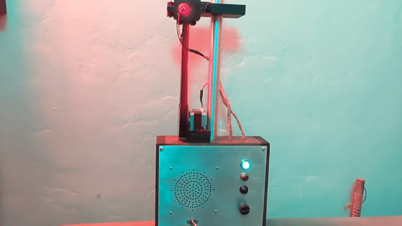
[Emily] used a pair of razor blades mounted to a 3D printed bracket to create the mask, and a TI OPT101 light sensor together with a light source to decode the optical signal. She tried to use a photoresistor and a discrete photodiode, but neither had the required sensitivity. She built a frame with adjustable positions for an idler pulley and the optical reader unit, an electronics box on one end for the electronic components, and another pulley attached to a stepper motor to cycle a short loop of the film.
Most of the projects we see involving film these days are for creating digital copies. You can digitize your old 35 mm photo film using a Raspberry Pi, some Lego pieces, and a DSLR camera, or do the same for 8 mm film with a 3D printed rig.


It makes me wonder what resolution you’d get with a cheap laser pointer, an optical mouse and a finer gap between the razor blades.
ideally you would take a gap the same size as the one they used to record the sound with as a smaller one only increases noise: on one side as there is no more resolution in the optical data and the only thing left is noise, on the other side, you get less light out of the gap so the gain should be higher, introducing amplifying noise. the sound fidelity on 16mm is not that great in the first place. later when they used magnetic striping the quality improved a lot.
Looking at the only part I know for an optical mouse, it does provides access to the raw pixels from the camera, which is 18×18 pixels (324 pixels) and each pixel can have a 6-bit value.
(for the datasheet “ADNS-2620 Optical Sensor filetype:pdf” in your search engine of choice)
Which mouse sensor are you thinking about ?
For reference, 16mm film has 40 frames/ft, so a 24fps film moves at about 7.2 ips. If that were magnetic tape, that would give you a pretty excellent soundtrack*, but alas, optical tracks don’t have that kind of resolution, probably owing to a minimim slit size needed to get a practical amount of light for the detectors of the day.
At 7.2 ips the optical wavelength of a 5Khz signal (telephone quality) is about .0014″ (.036mm), and that’s going to be close to the practical resolving power of the film after printing, at the equivalent of about 30 lp/mm. You’d need a gap about 1/3rd that width to reasonably track a signal of that frequency.
So.. that’s your minimum gap for the ultimate sonic glory that was 16mm educational film.
Ah… just listening to that warbling tone brings back memories from 11th grade health class and drivers ed. Gotta go Google if anybody ever put “Blood on the Highway” online.
Also, along a different line of musing, if you scanned the frames at some reasonable resolution, say 720 or up, you could probably algorythmicly reproduce the sound from the scanned image, just by averaging the horizontal lines of pixels in the soundtrack area. This is, in fact, what happens in modern 35mm films, where there’s an array of pixels in some otherwise unclaimes spaces around the frame lines and perforations which provide a high-fidelity digital track.
One issue you’ll run into is that the soundtrack is offset from the actual frames by several inches. The film going through the [projector gate moves intermittently, it pauses in the projection gate 24 times a second. Several inches after the gate the film goes back over constant-speed toothed sprockets which (more or less) restored linear velocity to read the soundtrack, but that means the soundtrack is “pulled up” several inches ahead of the matching frame, always an issue when a film had to be spliced.
* some film formats, including 16,35 and 70mm did have provisions for magnetic tracks, though except for 70mm, these were rare in practice
I think bloody asphalt was on vhs in the early 90s
Cool project… The opening image of you with your device and the parasol behind you made me think of Kaylee Frye from Firefly. She was a techie as well…
Neat project. The OPT101 is a pretty cool part. Any idea what was historically used for this task? Photomultiplier tubes?
Just a ‘regular’ old phototube. Like this!
https://en.wikipedia.org/wiki/Phototube
Ah! It even says so right there in the wiki! I must have forgotten all about these or I didn’t even know about them. Thanks.
I went down the Wikipedia rabbit hole, which led me to a link relative to my current interests:
https://mysite.du.edu/~etuttle/electron/elect30.htm
with the following sentences going back to this subject and piquing my curiosity:
“The first commercial use of phototubes was in the reproduction of sound from motion picture films. The sound was recorded as a variable density sound track that was naturally synchronized with the pictures. Though the film moves in jerks in projection, it must move at constant speed in the sound pickup. This was an interesting technical problem, whose solution was ingenious and practical.”
After searching a bit for technical details, I came across an excellent (as usual) Bill Hammack video on how the whole projector mechanism works. Ingenious and practical solution indeed!
[youtube https://www.youtube.com/watch?v=En__V0oEJsU&w=560&h=315%5D
Super cool project, neat to know about the opt101 and its performance.
Was there a reason not to digitally ‘scan’ the strip and reconstruct the signal digitally? I’m also considering a project like this, so I’m curious to learn from those who have tried it before. Thank, Emily!
No reason besides it just didn’t appeal to me? I mean, I could just feed the audio output from the sensor right into a USB audio capture device and record it digitally, but I really enjoy working in the analog realm.
Makes sense. I perfer to live in the digital one. :)
My mind leaps to an optical Mellotron. I’m trying to think of a way to print film loops that as easy as making magnetic tape loops.
You can easily source continuous clear thermal label stock in various widths for use in ordinary label printers. The only remaining problem is finding out which chemical actually dissolves the adhesive!
I’ve been experimenting with this, and it can be done somewhat crudely by printing patterns from photoshop or illustrator onto transparency sheets with laser printer. There’s a bit too much work involved in cutting the sheets into 16mm strips and then splicing them together, and the DPI of the printer means you can’t get anything too high fidelity with it, but it does work. You can see one of my experiments here:
https://twitter.com/MLE_Online/status/1341469464131321856
This is awesome. I think it’d be cool to make a DIY Variophone. What, you haven’t heard of the Variophone? [Check this out!](https://www.youtube.com/watch?v=4r4WqAf-X8Y)
AEO Light is a great bit of free software that reads optical film tracks digitally. https://usc-imi.github.io/aeo-light/
This brings back memories of threading the 16mm projectors in elementary school and jr. high. They were ancient even back then. I remember they used an exciter lamp which was a special incandescent bulb with a straight filament and prefocus base. Times have changed.
I’d be interested in a schematic and parts list