Fused Deposition Modelling (FDM) 3D printers which squirt out molten plastic layer by layer are by far the most popular type in general use. Most machines extrude plastic through a nozzle above print bed, and struggle to produce parts with overhangs without using support material. However, a German team of researchers have recently come up with a solution.
In a prototype built by researchers at the Zurich University of Applied Sciences (ZHAW), a standard Cartesian printer has a third rotary axis added, upon which the nozzle can rotate. Additionally, the nozzle is angled at 45 degrees to the print bed, rather than the usual perpendicular setup. This allows layers of a print to be built up in such a way that support material is not needed for the vast majority of typical overhangs. This is particularly useful for hollow parts, where removing support material can be particularly difficult.
The team believes that such technology could be implemented on existing printers by way of a simple upgrade kit, and we can imagine a few experimenters will be champing at the bit to try it out. If you do, be sure to drop us a line. Alternatively, consider using a marker to make removing supports easier. Video after the break.
[Thanks to Andreas for the tip!]


What a lack lust article for such a superb design.
This is easily the best design I’ve seen for a 4th axis on a 3D printer. Minimum complexity for maximum utility.
Try printing miniatures or something more complex. You will still need supports. They only demo for a simple shape with a 45deg overhang and some holes with small bridging. This doesn’t make this the go-to for more practical use.
Isn’t Zurich in Switzerland?
Zurück is back in Germany. … ;-)
I see what you did there. ^_^
Sure looks like it. Their website is .ch
Though they are speaking German
Swiss people have actually 3 native languages to select from, when talking. Though all of the domain endings are .ch
They have at least 4 languages. Maybe you forgot Romansh (I’m not sure if this is the right english translation, in german it’s räto-romanisch).
Yes! https://en.m.wikipedia.org/wiki/Zürich
Switzerland has 4 official languages, German, French, Italian, and Romansh (a descendant language from Latin). In the German speaking portion of Switzerland (which Zürich is in) many/most Swiss will speak Swiss German, a distinct dialect with a different pronunciation and many different words than German. The dialect is mostly only spoken (although it does get used in written form in many informal settings like social media), typically however for formal settings like the news, school/university etc. German is used.
Yes it is :-D
I don’t think the video really demonstrates it printing an overhang. I was expecting a time-lapse of a 90 degree overhang.
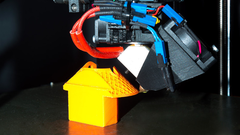
The article image shows a 90 degree overhang…
Yep, there is an image of an overhang that has already been printed, but I would be more convinced with an actual video of it being printed. It would have been an obvious bit of corroborating evidence. I kind of get the idea they are using but I am not totally convinced that you can avoid all distortion under gravity just by changing the angle of the nozzle head.
They are not just changing the angle of the print head, but printing in conical layers instead of flat ones. I think that’s the other half of the invention if I understand the video correctly.
Sure, add more weight to a DD.
Hmm, I must disagree with the comments above me. I don’t think this design for an extra axis is good.
First think about the cable management to the hotend. These 4-6 cables for the heater, temperature-probe and fan are going to be twisted a few thousand times in just a few prints, making them to have stress points that could create resistance points in the cable or even worse, making them to break.
The second reason is… look at that head… it is outrageous, to say the least. I am sorry for my german counterparts, but just look at it. It has the extruder motor and the rotation motor stacked on a vertical axis, creating a long vertical mass that will twist on high velocities. Also… where the heck does the filament run through? I mean, does it go by the extruder motor, to a teflon tube, through a bearing, to the hotend?
Looks cool, but I don’t think it is a viable solution. It just adds to much complexity to a problem that isn’t really a problem if you design your pieces right
I also don’t get why there are so many 5 axis printers now… What is the point? To print without supports? A few years back there were some really great designs that could set the hotend in any angle and position and they didn’t caught up in the market because they added to much complexity to a system that didn’t need it, but wanted to get dirt cheap
I totally agree to everything you say, except one little point, which is the wire twisting issue. I haven´t yet checked the design of this particular printhead, but If I had to design such a system, I totally would use slip rings which are perfect for such an application. IF I had … good engineering is when you manage to reduce complexity in order to solve even more complex problems. Modern slicers have grown to minimize the problems with overhangs and support material to a bearable minimum. When I look back to the early reprap darwin and mendel days where overhangs were considered to be impossible without supports and compare to what we have now with esentially the same technology but many small and clever improvenments here and there like part cooling and all the software side hacks, I must say we have come a long way.
cabl managment is the least problem i guess if a see a robot doing 360 degrees movements every day and yes they are cabled
Because they use slip rings, this is what I said. Did you read what I wrote before answering to my message?
Slip rings are rarely used in 6 axis robotic….slip rings are used on multi station rotary tables and also some trunion style indexers but its usually the last resort as slip rings tend to have issues
I feel like you way over exaggerated a lot of things here.
First, you act like current 3D printers (and other machines) don’t have moving/twisting axis’ that cables have the run though. If you put enough slack in them, which it appears these engineers did, you don’t have to worry about fatigue points. Also, you can limit the rotation of the axis to 1 revolution too, meaning it won’t continually spin, wrapping itself up in its own wiring, this not being an issue for the cables. As for the filament, it’s the same deal. Slap it in a caption tube and you can move it around a bit, no problem, just like on other printers.
Second, this is a PROTOTYPE or PROOF OF CONCEPT, not a finished product. You’re worrying about product refinement whereas they just finished an alpha or beta build. Go back 5-10 years and look at what printer extruders looked like and then compare them to today’s design, it’s a night and day difference (my first printer had a stacked acrylic extruder housing). So, as they go though product refinement, I’m sure they’ll experiment with the use of smaller steppers and probably even a bowden extruder setup.to make the whole mechanism smaller.
Third, you say the design is “too complex”, yet I’m sure people said the same thing when standard eD printers came out, not to mention that the design isn’t really all that complex, they make CNC mills with 4 and 5 axis capabilities. What it really comes down to is marketing and cost. If they are are horrible at marketing their product (which, if the supplied video says anything they are) and then go on and charge $5000+ for the product, it won’t catch on. On the other hand, if they do a decent job marketing and charge a reasonable amount for it (and don’t parent the crap out of it, which is typically what prevents things from catching in), then it will probably be implemented quite easily. I mean, look at the new belt printer from Creailty. It is also a “complex” machine, but they’re doing a good job marketing it and put a decent price on it at $1000, and from the sounds of things, people are lining up to purchase it.
Now, I’m not going to sit here and say that this is perfect, I just don’t get your ridiculous critique. The whole “extruder at 45°” thing is weird and I would imagine will cause adhesion issues when compared to normal perpendicular designs. Also, I feel like, if you’re going to add a 4th axis, you might as well just go and add a 5th axis right away and be done with it as that will get rid of the needed “extruder at 45°” thing.
It’s using slip-rings. Not an issue. No wires are being twisted.
Hmm, I must disagree with the comments above me. I don’t think this design for an extra axis is good.
First think about the cable management to the hotend. These 4-6 cables for the heater, temperature-probe and fan are going to be twisted a few thousand times in just a few prints, making them to have stress points that could create resistance points in the cable or even worse, making them to break.
The second reason is… look at that head… it is outrageous, to say the least. I am sorry for my german counterparts, but just look at it. It has the extruder motor and the rotation motor stacked on a vertical axis, creating a long vertical mass that will twist on high velocities. Also… where the heck does the filament run through? I mean, does it go by the extruder motor, to a teflon tube, through a bearing, to the hotend?
Looks cool, but I don’t think it is a viable solution. It just adds to much complexity to a problem that isn’t really a problem if you design the piece right
I also don’t get why there are so many 5 axis printers now… What is the point? To print without supports? A few years back there were some really great designs that could set the hotend in any angle and position and they didn’t caught up in the market because they added to much complexity to a system that didn’t need it, but wanted to get dirt cheap
More axis in printing has lots of potential benefits
– Overhangs not needing support is the obvious one
– No infill needed – potentially for some more hollow vase mode like hollow prints – those with complex geometries you want to be hollow – perhaps for cable passages (like the printable RC aircraft?) – Currently you have to have complex hard to create infill for support because the printer has to print everything in the same orientation, or use a resin printer, and no resin has the same mechanical properties as even the common easy FDM materials (and sometimes that matters).
– strength – by printing the right sections of each part in the right orientation you can keep the layer lines in the right orientation for the load of the part (or even theoretically print in infill layers in one orientation and the outer shell layers another for that laminated structure)
– better surface finish – theoretically having 5 axis you can print the outer skin in the best orientation for smooth/detail and at the best time (after the infill has cooled some for instance) as its possible to print over existing shapes
If it will ever be part of the cheap end consumer printers? Any time soon I seriously doubt – in the same way desktop and budget CNC subtractive manufacturing machines are almost all only 3 axis. But its an ability with potential if the slicing up of your model into gcode in the right ways can be solved.
Could a polar printer produce the same results with a 45 degree tilt without the complexity of adding another axis.
No. You can’t control which direction the nozzle is pointing without also changing the position on the build platform.
Its not quiet a flat no, as for most models being built centred on the plate the need to rotate the nozzle around them separately would be very low, if not zero – so a workable compromise for some users.
Also a good idea perhaps to base this sort of printer of a polar design – could perhaps do away with the slip rings that would definitely be needed in this design – when needing to rotate the head further than the stops that protect the wiring will allow just remove the head from the build space and unwind, but as most of the time this isn’t going to be needed its a cheaper machine to build.
Hi, cabling should not be a big deal if a high quality “slipring cable” is used, they are used e.g. tape libraries hp msl-3040 to connect the robot cable spool and they are have millions of expected/tested working cycles. So you have not even to worry about limited rotation.
And the filament can just be routed through the center. You may have to look with the rotations like try to only do 360 but that would be a software thing.
I guess the software and it’s open sourceness would be the biggest problem from my point of view.
This could solve metal 3D printing for the household. Put a mig on the end of that, and a CNC directly accross from the print head. Boom. Cheap metal 3D printers.
“Boom”, eh? That simple?
Ever **used** a MIG welder? To name a few issues:
– Metal spatter
– Surface tension
– Liquid metal flows downhill
– Oxidation
– Tuning voltage and current based on what other metal is actually present (affected by previous factors)
– Weld penetration
– Residual heat / workpiece temperature
Possible, perhaps. Simple, no.
There’s already people putting mugs on 3D printers. The only problem is the inconsistent layer height. Hence the 4th dimension and the CNC milling head.
I’ve spent some time playing with this, and I think a better design would be a wirefeed head using a TIG torch and a cold-welder setup, where you get dozens of millisecond long bursts of current, that welds each pixel of your growing print. It’s still not going to have high resolution, but the argon will help solve oxidation (at quite an operating price.) It’d be similar to FDM in that it wouldn’t have great interlayer adhesion. But it might work well if you need something metal with 2mm minimum resolution.
The whole “welder 3D printer” has been tried many times, and it doesn’t work too well. Then, having to machine the part of top of it adds a huge point if entry for error in the part. I’ve seen it done kind of well, but it’s not as easy or reliable as you think it is, and ,due to the multi-process complexity of the machine, not to mention the necessary rigidity of such a design, it would.probably cost you atleast 10k, if not more, which puts you close to a cheap industrial level pricetag anyways, and they quality they produce is going to beat your welder/mill combo all day long
The bigger problem that I see here is the limitation on the files that you could print. Say you were printing something with a heart shape, and anything that has that divot like at the top of the heart, you would risk having that twisting printhead gantry risk running into the rest of the print and knocking the print off the buildplate.
I don’t follow, could you explain what you mean? I’d have thought that, from the perspective of any one flat layer, it doesn’t matter if there is going to be material above (the lumps on a heart) or not (the divot)
You could run into a problem if the slicing isn’t done conically – if it stays strictly layer by layer vertical printing than the two separate bumps at the top are sticking into the same space the head would occupy.
But if you slice the build knowing this its no problem – as you can see in the image above its all infill in a cone as the print builds out from the middle to avoid this issue.
What the surface finish and structural integrity will be like with this very different print structure could be interesting to study.
He is using simplify 3d for Gcode generation… I wonder how he is converting the Gcode to tilted 4th axis.. Simplify3d IMHO can’t do that…
They’re probably just using the gcode viewer in Simplify3D, it’s a pretty nice viewer.
This would be perfect if it would be added to a belt printer. With this the problem with the bed and nozzle being at an angle could be removed. In addition to better overhangs printing actual 3d and not 2.5d for things like the top surface could be a plus. My only concerns are by this would be implemented and supported by slicers. The added complexity could also be a problem , like the fact that my printer has 2 nozzles but I rarely use both because of the bother.
What an interesting design. From what I could gather from the photos on the ZHAw’s website. The key to this design is a hollow stepper for the added axis, and a custom hot end. The Hotend looks like a drilled out volcano block. Everything else is easily 3d printed, or off the shelf parts. Found a hollow NEMA17 stepper on line for $50. Pricy but not cost prohibitive. This design really lends itself to all sorts of improvements. First off that NEMA 17 stepper for turning the hot end is way over kill. Just to turn a Hotend and a fan. Next might be a Bowden design just to help with lowering the mass of the Head unit.
Sadly, The science article is pay walled. https://link.springer.com/book/10.1007%2F978-3-030-54334-1
Thoughts?
This is an interesting idea but I don’t think they sell it very well.
They focus on the elimination of supports, but that may not be the most useful aspect of this design. They state in the video that removing supports allow for faster printing times, but allow me to doubt that : with this much weight added on the head, you need to turn down printing speed a lot to avoid flex and vibrations, and this would cancel any time gain on most geometries.
However, tilting the print lines at 45° could be very interesting on some parts to improve mechanical resistance in the Z axis by spreading forces on larger surfaces and avoiding weak points around horizontal surfaces. Same reason the default infill on most slicers is at 45° and -45° in the X/Y plane, because most external surfaces will be at 0° and 90°.
It could also have interesting esthetics applications.
Looks like a useful technique for some particular geometries, even though definitely not as quick and versatile as the standard setup.
In any case, I like the spirit of “I’ve got an idea, let’s build it then see what it could be used for”.
There seems to be an much simpler solution than the one shown and it gets rid of all the cabling/slipring/weight issues. Take a typical extruder and create a mount that positions it at 45 degrees like in the video. Just be sure that in the 45 degree position the nozzle is the lowest part. Then make a mod to the build platform that can rotate the part being printed like a driven lazy susan. Minimal weight added to the print head and no cabling issues.
Given the printheads movement, the slicer to Gcode translation is the hard part.
I think that everyone in the comments has completely forgotten about the idea of “proof of concept” designs. This isn’t a final product, it’s probably like a second or third prototype, still in apha or early beta. So, all your comments of “it’s too big and clunky” or “slicing for that is going to be difficult due to the printhead design” are all probably being worked on as we speak.
Having a print head angled at 90 degrees aids in the filament being slightly squished onto the prior layer for adhesion, thus making the model structurally stronger. How does angling the head at 45 degrees help with layer adhesion since it doesn’t seem like the layers are getting squished onto each other? To me, angling the head in this way wouldn’t make your model very strong since its simply laying the filament down as its being extruded.
A good question, but I don’t think its going to be quite as bad as you envision – each layer is still going to be smashed into the previous one as the head is staying at the z step distance, and the previous layer is already at the same orientation.
Getting initial bed adhesion for this reason I think will be the hard part, once its printing I don’t think it will make much difference to how the layer boundaries are – and because its a conical print I expect its actually stronger – getting the layers to separate is going to be much harder I would think – as each layer isn’t shearable in x,y plane..
Here I was hoping the whole printer would do a 45 tilt and gravity would be coming from another angle
Me too, it makes a lot more sense to constantly keep head and printing spot vertical and use gravity instead of creating a lot of exceptions to get around it.. and if you want to print something , and i don’t see this design printing something drooping down ( and printing at 90 degrees seem to require a slanting angle to build on)
But that’s my un-professional option (i’m not in the field of designing 3d printers)
I think a double-polar printer might work just as well and be simpler. E.g. suppose that the bed can be rotated (yawed), and the print head moves vertically and along one horizontal axis and can be tilted (either rolled or pitched).
This functionality is already there. I’m just wondering why it isnt being used yet. The heveort implemented last year april, and the new ratrig has it. We just need the support to utilize it properly and that needs to come from the slicer side, and maybe the firmware.