
So far in the $50 Ham series, I’ve concentrated mainly on the VHF and UHF bands. The reason for this has to do mainly with FCC rules, which largely restrict Technician-level licensees to those bands. But there’s a financial component to it, too; high-frequency (HF) band privileges come both at the price of learning enough about radio to pass the General license test, as well as the need for gear that can be orders of magnitude more expensive than a $30 handy-talkie radio.
But while HF gear can be expensive, not everything needed to get on the air has to be so. And since it’s often the antenna that makes or breaks an amateur radio operator’s ability to make contacts, we’ll look at a simple but versatile antenna design that can be adapted to support everything from a big, powerful base station to portable QRP (low-power) activations in the field: the end-fed half-wave antenna.
Making a Match
There are plenty of hams out there for whom antenna building is the be-all and end-all of the hobby. I get that; there’s a non-zero amount of wizardry that goes into designing an antenna that will do what you want it to do electrically, and plenty of engineering involved in making sure it stands up to the elements. I think the latter aspect of antenna building is more attractive to me personally. Getting an antenna to survive wind, snow, sun, and rain is an interesting challenge, so I tend to spend more time thinking about the mechanical aspects of design that someone has already worked the RF bugs out of.
So I set out looking for an antenna that would work for my situation. Perhaps the easiest antenna to build is the classic half-wave dipole. These have two elements, each one-quarter of the design wavelength, radiating out from a central feed point, which is where the coaxial cable feedline attaches. There are elaborations and complications, of course, but the basic issue for me is the central feed point. My shack is located at the very back corner of my property, so it’s difficult to rig an antenna like that without a long feedline, which can introduce unacceptable signal losses. Plus, a dipole for the 80-meter band would be 40 meters end-to-end, and that would be hard to fit across my long, narrow suburban lot.
For my purposes, the end-fed half-wave (EFHW) antenna is a good choice. It’s exactly what it sounds like: a chunk of wire one-half of a wavelength long (in my case, 40 meters long so I can work the 80 meter band) that is fed from its end. But it’s not as simple as cutting a 40 meter long piece of wire and sticking it on your radio. The problem is that the impedance of an antenna varies as the feedpoint moves away from the center. The impedance increases all the way up to about 2,500 ohms when the feedpoint reaches the end of the wire, which would be a very bad match indeed for a transceiver expecting a 50 ohm load.
To fix this, EFHW antennas need a transformer to match impedances. When used to match impedance between a balanced antenna, like a dipole, and an unbalanced feedline, like coaxial cable, these are referred to as “baluns”. In this case, though, both the antenna and the coax feedline are unbalanced, so the transformer I built is technically an “unun”. Whatever you call it, it’s a pretty easy build.
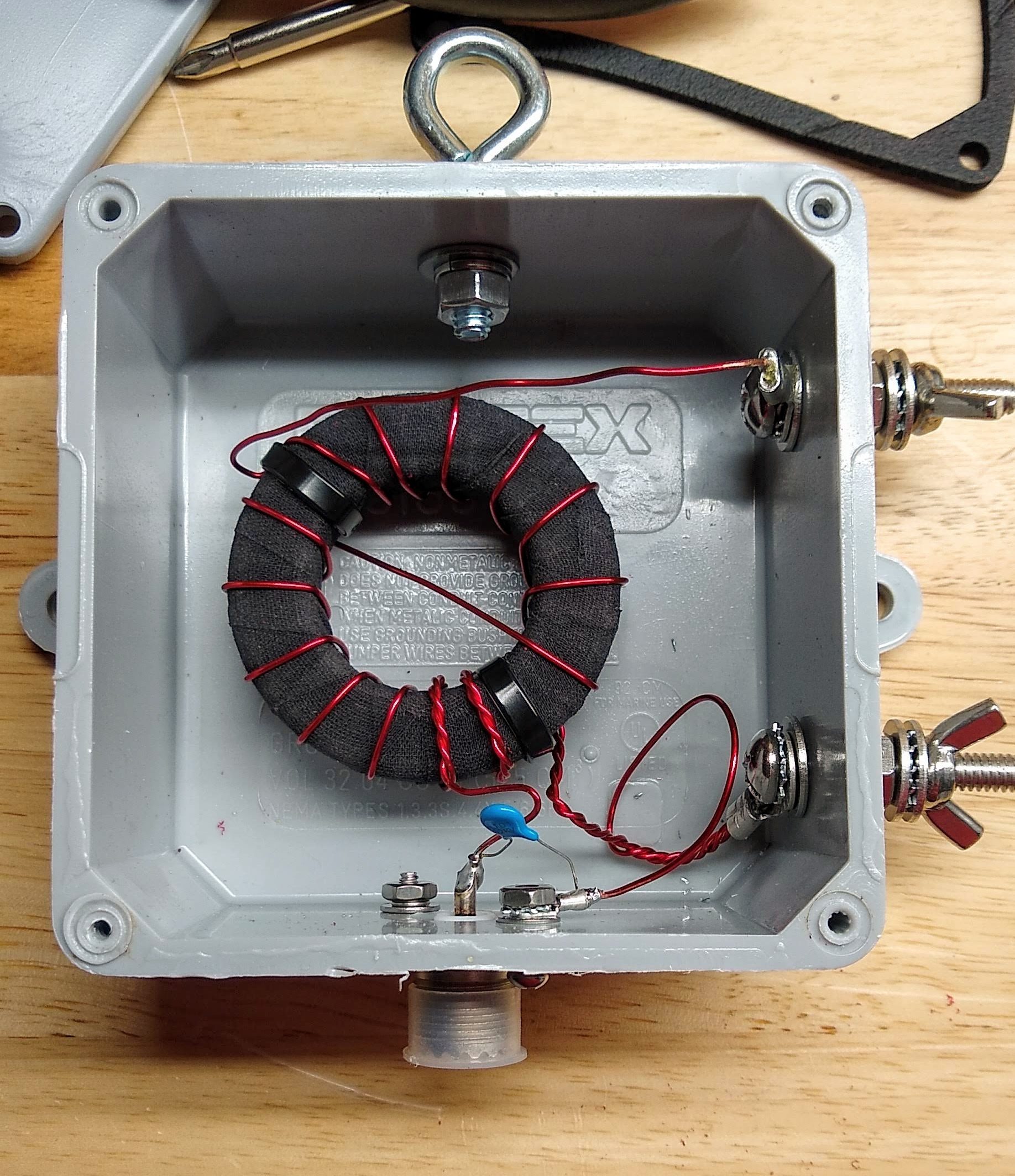
I followed the excellent instructions provided by Steve Nichols (G0KYA) to wind my 49:1 autotransformer. It’s basically just big ferrite toroid core — I got mine from eBay, but there are plenty of options on Amazon — with a few windings of magnet wire. My core is an FT-240-61, which means its outside diameter is 2.4 inches and it’s made of type 61 material. I used 18 AWG magnet wire for the windings. While I was winding it, I noticed that the lacquer coating on the magnet wire was getting nicked by the edges of the ferrite core. I rewound it after covering the toroid with cloth friction tape to cushion the edges a bit — shorts would be no bueno in something designed to handle 100 Watts of transmitter output.
Like I said, a lot of the fussing I did with this transformer had to do with making it work mechanically. I mounted it into a sturdy plastic electrical enclosure and provided stainless steel fittings for connecting the antenna wire and the ground connection. I also installed an eye bolt to tether the antenna wire. A good-quality SO-239 socket for the feedline connection and a 100 pF high-voltage capacitor for better matching on the higher frequency bands completed the transformer. With luck, this antenna should cover 80 m to 10 m bands.
Pushing Rope
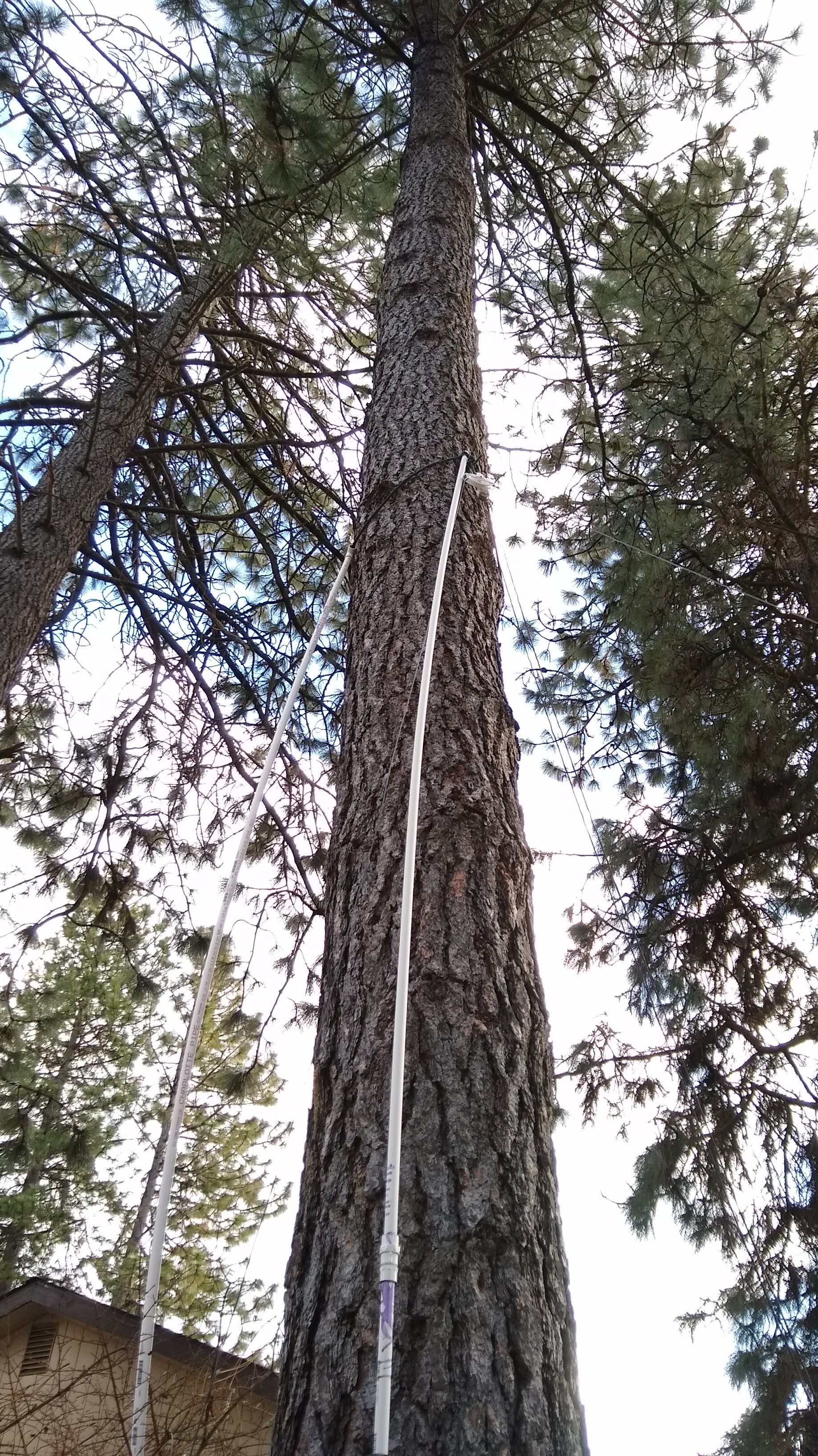
As luck would have it, my lot is just about 150 feet deep, and I’m both blessed and cursed by a lot of very tall, very sturdy Ponderosa pines. The length of my lot and the location of the trees allows for a full 40-meter wire in a sort of “inverted-L” configuration. My plan was to slope the wire from the transformer up as far as possible in the first tree, then run it horizontally to an anchor point in a second tree.
This sounds far, far easier than it actually is. While many hams have had good luck suspending antennas from lines lofted over branches, my pine trees have all been pruned of their lower branches, with the first living branches more than 40′ (12 meters) above the ground. I opted for a “work smarter” approach and came up with an idea to basically push a loop of rope up the tree using PVC pipe as a push stick. Although the roughness of the Ponderosa bark constantly snagged the nylon rope and the PVC pipe flopped around as I added sections , it actually worked well enough to get the anchor point about 25′ (7.5 m) above the ground — not much higher than I could have gotten with my 24′ ladder, but with a whole lot less risk of falling to my death.
The anchor point was set in the other tree using a similar method, which drew a lot of attention from the neighbors. One should always seize such opportunities to do a little “ham goodwill” outreach, and I assured the neighbors that I wouldn’t be sterilizing their kids or interfering with their TV reception. In an example of karma, though, the tree I was working in decided to shed a dead branch the next day, which came down and damaged my neighbor’s Durango. It clearly came from much higher in the tree than I was working, but it still caused a little bit of the old stink eye.
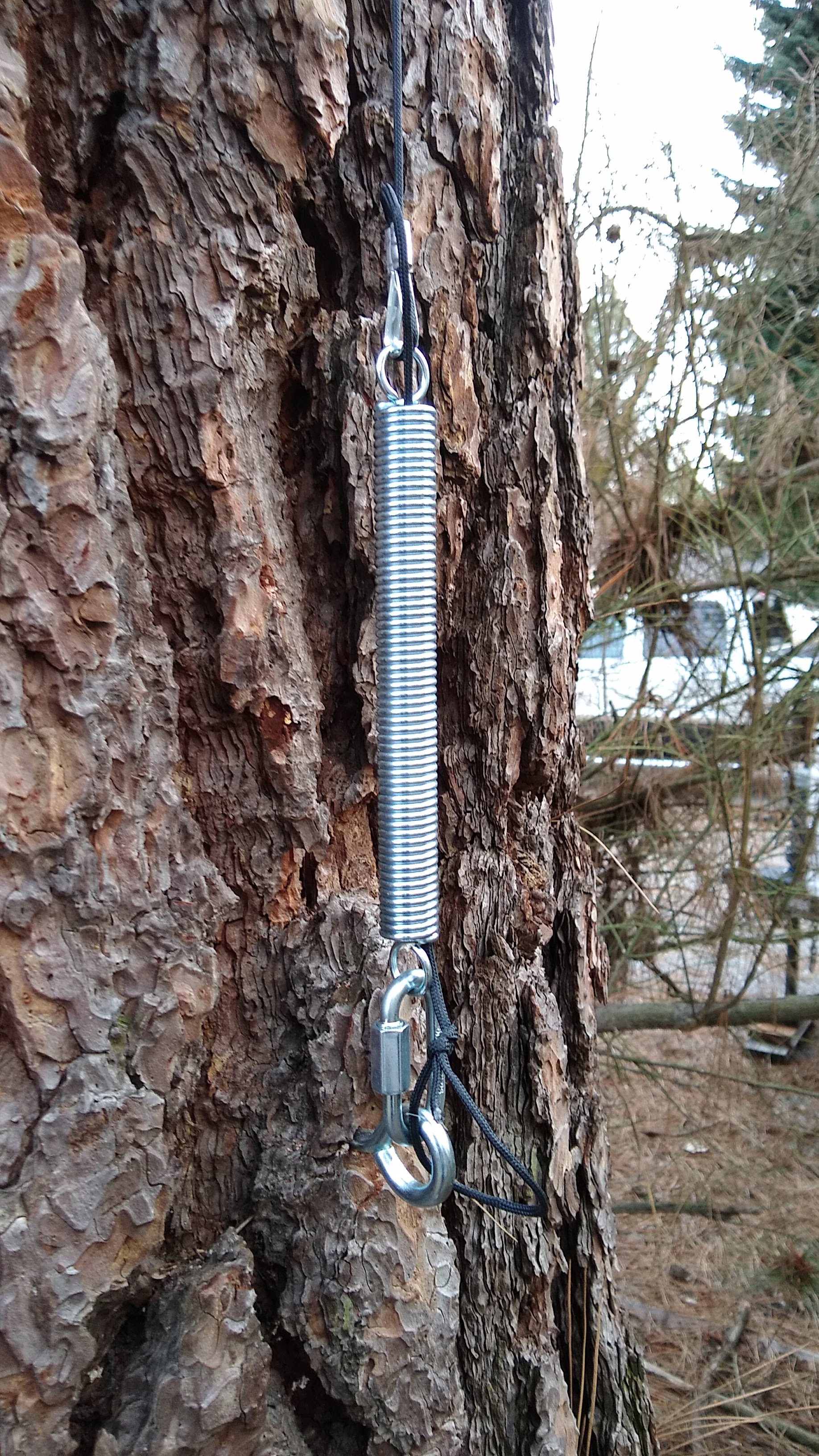
One of the most important parts of using trees as anchors for long-wire antennas is dealing with sway. Trees move around quite a bit, and if you anchor a wire tightly between two trees without allowing for them to move with the wind, sadness will ensue. And yet, you want your wire to stay more or less taut, since its shape affects its performance. There are a couple of ways to deal with this, and I chose to use clothesline pulleys at both my anchor points. At the midpoint, the wire runs through the pulley; at the end anchor, the wire is tied off to a length of strong nylon cord through a dogbone insulator. That cord runs through the pulley and down the trunk of the tree to an anchor point through a strong spring. When the trees sway, the antenna can extend or retract by several inches without sagging or snapping.
On the Air at Last
I have to admit that this installation isn’t actually complete yet. Antennas really should be properly grounded, and I’m keen to pound a ground rod in near the transformer. However, both the mains feeder for my house and the primary feeder for the entire neighborhood are buried directly under our back fence, making this a high-risk endeavor. As good as underground location services are, I’m not keen to test their precision with my precious self. So I’m going to wait for a decent ground.
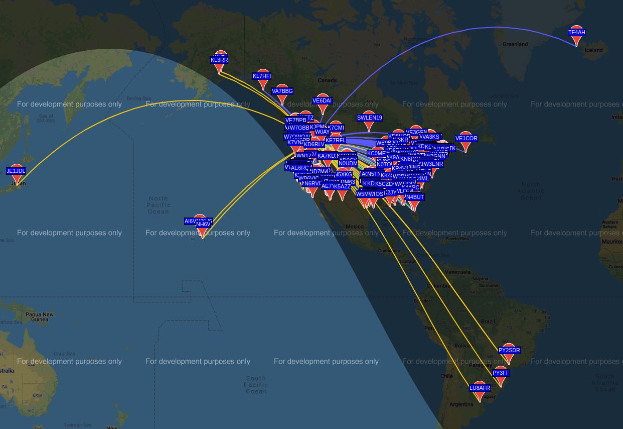
Still, I couldn’t help but want to try this antenna out, so to keep RF out of the shack, I wound a 10-turn air-core choke on the feedline and hooked it up. I haven’t made any QSOs yet, but using WSPR, the Weak Signal Propagation Reporter system, I was able to reach four continents over a 24-hour period on the 80-, 40-, 30-, and 20-meter bands.
And speaking of WSPR, that and other digital modes are what we’ll be talking about in the next installment of the $50 Ham. Spoiler alert: despite my previous gripes, I think I’m falling in love with ham radio again.


One of the great advantages of an end-fed half-wave antenna is the fact that they usually do not need a counterpoise! (as far as I’m aware) Or, as I understand the RF magic of them, they kinda are their own counterpoises.
I use an end-fed half-wave as my mobile antenna, and it has served me well over the years. Of course, it’s only about a meter long (cut for the 2m band), so it works quite well mounted on the roof of my car without the worry of scraping the bottoms of passing airplanes. The lack of a need for a counterpoise (aka RF ground) allows me to use a mag-mount antenna base without losing antenna performance, as well as mount it anywhere on my car that is convenient. I’ve even lent the antenna to a friend of mine to use on his snowmobile! (for those curious, the antenna is made by Gam, division of Yankee Microwave Inc., model SS-2)
EFHW, work much better with a counterpoise, or radials. Your 2M mag mount has one, it’s the roof of your car. “Ground” side is capacitive coupled to the sheet metal.
The ground plane is like a mirror. Easiest way to think of it I think. When I was last futzing around with CB, set up one of those “Emergency” kits in the car, must have been a 1/8 wave antenna. I put it square in the middle of the roof and I was getting “skip” from 1000 miles away.
Not to sound argumentative, but I was never able to see a performance difference between using a ground plane (car roof) or no ground plane whatsoever (snowmobile). I have used the same antennas in a number of other locations, and they have never required a ground plane of any kind. That is one of the great things about them, you can literally put them anywhere (book shelf, fiberglass car, snowmobile, apartment window, etc.) and they tend to work quite well.
According to my understanding, an EFHW acts as if it were a dipole (a pair of 1/4 wave elements, in other words), but are fed from one end instead of the center. Dipoles do not require an external counterpoise, as half of it IS the counterpoise.
Do they work better with a counterpoise at lower HF frequencies? I have no idea, all of my EFHW experience is with VHF and UHF antennas.
It’s my understanding, that the ground itself acts as a lossier ground plane still until you are many wavelengths above it, just the effective impedance between the real element and reflected element gets greater and greater the further you are from it. So snowmobile lower to the ground than car, on snow, might have had better effective ground plane than you thought.
Drifting off topic. At VHF or uhf you may not hear the difference a ground plane makes… doesn’t me the guy on the other end or the repeater doesn’t! At HF the counter poise at a minimum reduces the amount of transmit energy absorbed by the earth which is then converted to radiant heat rather than launched into space. Again you may not hear a difference but the other guy may depending on TOD, take off angle, conditions of the F1and F2 layers, etc.
Also an end-fed wire in an inverted V configuration might be fun to try.
Enjoy
Mag mounts use the car’s metal body as a ground plane. I have an old metal bookshelf that I use in the house for a mag mount. Also a 2×2 sheet of steel for use on vehicles that don’t have metal bodies, i.e. some ambulances. Duct tape the sheet to the roof so it doesn’t blow off i you end up transporting someone at 80 mph.
The need for counterpoise of EFHF is a (surprisingly) controversial topic, I know, but the thinking is that if you do not provide an deliberate counterpoise, then the shielding of your feedline effectively becomes the counterpoise. So it’s there even if you didn’t put it there.
More deets, for the curious:
http://gnarc.org/wp-content/uploads/The-End-Fed-Half-Wave-Antenna.pdf
(p13), and:
https://web.archive.org/web/20181018145410/https://www.w8ji.com/end-fed_1_2_wave_matching_system_end%20feed.htm
“so the transformer I built is technically an “unun”.”
Love it!
B^)
unun = Unbalanced to Unbalanced, balun = Balanced to Unbalanced
Great job Dan. I wish I had your trees in my yard!
73
Charlie ZL2CTM
Until a storm knocks the tree over and it goes through your roof.
Strangely enough, we just had an epic windstorm that knocked over a lot of trees in the neighborhood. We came out unscathed this time, but a lot of people weren’t so lucky. I’ve been hearing the buzz of chainsaws and chippers all day, in fact.
Lot drainage can play a part too, evergreens are shallow rooted, so if the ground gets sloppy and there’s high winds too, over they go, roots and all.
Spruces and Lodgepole Pines are extremely shallow rooted, but Ponderosa tend to have very deep roots. Having pruned them up nearly 40ft would be a key to their wind survival . While the crown still caught a lot of wind, the moment arm length of the stem absorbed the wind force before getting to the roots
Thanks, Charlie! The trees are a blessing, and a curse. Aside from the risk of falling over, the thing nobody tells you about evergreens is they’re also “everbrowns” — Ponderosa pines are constantly shedding needles. They lose a third of their needles each year, pretty much year round. We’ve cleaned up several metric tons of needles in the four years we’ve lived here. And the pinecones are deadly — huge and with sharp points on the ends of each scale. Very painful to step on in bare feet.
An abundant supply of smallish regularly shaped organic matter is something that is more easily screw fed into things like gasifiers, if you wanna screw with needle powered IC engines, heat or backup genny etc.
My recommendation for buying toroids: https://kitsandparts.com/ It’s run by a ham, W8DIZ. They have all the toroids you will need at good prices and you’re assured of getting quality parts, and also offer other things you may need such as magnet wire and silvered mica capacitors.
Diz does ship internationally but the costs are likely to be high. This recommendation is primarily for people in the US.
Fake toroids that don’t match their purported characteristics or have excessive losses at RF are sometimes an issue from eBay and AliExpress sellers.
I love kitsandparts for their large selection and prices, and have a bunch of torroids from them. However, on this particular ring, it is surprisingly cheaper from Mouser — go figure.
https://www.mouser.com/ProductDetail/623-5943003801/
The price has risen since I bought a couple a few years back — was $usd4.55 at the time, now $5.95 — but still.
I did use the -43 mix rather than the -61 Maloney is using in his article because the -43 does a bit better at the lower frequencies. I also splurged and stacked two rings in my transformer for better power handling (not that I really expect to ever use that much power, but I bought two rings so why not).
Thanks for that info. Kitsandparts is definitely the go-to for Micrometals powdered iron toroids, which are not available from major distributors. The Fair-Rite ferrite toroids are available from Mouser and Digi-Key, so those sources are also worth a look.
sure! though much to my chagrin I have to ammend my prior statement. It was true in 2019 when I ordered that core for my project; then it was about a 2:1 cost ratio. However, as mentioned Mouser has since raised the (unit) price about 30%, and now checking I see that K&P have lowered their price to $8. (I can’t remember what precisely their price was then, but I wouldn’t have cared about a $2 difference at the time, especially since I was ordering other cores from them for that same project, anyway.)
Anyway, I do second your KitsAndParts mention; just sometimes it pays to shop. Cheers!
Thanks for the link
There are morse segments for techs on 80m, 40m, and 15m. You don’t need to use your brain to make or decode morse. I made a video about it a few years ago.
https://www.youtube.com/watch?v=qqLJop53Ybc
72 de N0ECK
A metal rod pounded into the ground is not useful as an RF ground (part of the antenna). A ground rod is a necessary part of your safety grounding system along with a lightning arrestor. Unless you want to fry your radio. For the RF part, you need the other half of a dipole, ground plane, a counterpoise, buried or elevated radials.
“My 49:1 matching transformer, mounted and ready to go outside. I considered potting the hole thing in epoxy, but decided against it.” I wholly get the joke here – I really do!
I wish I could take credit for anything but the typo. Sorry, had to fix it — but glad you got a chuckle.
Thanks for bringing this series back – I just got my Technician license a few weeks ago. Any plans to review some of the solder it yourself kits or other budget options for the HF bands to go with the HF antenna? I’ve been looking into the various QRP Labs and similar items. Kind of disappointed that there’s not much for 10 and 15 meters for good daytime propagation (and keeping the antenna small).
KO4KQP
Thanks, good to be back! I have considered some of the QRP kits as an article, so stay tuned. I also stumbled upon a one-transistor 40/30-m CW transmitter that I’m writing up as a daily post — pretty sure I’m going to build that and do a feature on it too. Getting an HF transmitter on the air is generally order of magnitude more than $50, at least for commercial radios, but throwing a couple of parts in a box seems more in keeping with the theme of the series. So watch for that too.
Don’t use that circuit. It’s a gimmick, if you have an RF power transistor, you have lots of small signal transistors to make a separate oscillator.
You can go back sixty years and endless simple transistor transmitters, which aren’t about as simple as possible.
Everyone should build a crystal oscillator, put a signal into a receiver, learn some basics, and demistify RF and all that talk about how fussy it is.
Then build a good transmitter.
Also keep in mind that a crystal controlled transmitter today is counter to most equipment, so you can’t move where people are listening.
Whatever happened to DSB suppressed carrier transmitters, voice and without the carrier, but easier to build than SSB. Most people will never notice the extra sideband on an SSB receiver.
Beginners shouldn’t be the final word on beginner projects.
If you’re new to soldering and building, check out some of the QRPguys kits. I’m not associated with either company, but know from 30+ years of building experience the QRPLabs kits can be challenging.
73
New to ham, not new to soldering and electronics. I hadn’t seen the QRP Guys kits before. Most of the interesting transceivers aren’t yet released, though.
So far as I can tell, all of the QRP Guys receiver and transceiver designs are direct conversion. It’s important to understand the advantages and limitations of that kind of receiver.
Pure direct conversion receivers (minimal or no audio filtering, no phasing or DSP) have a sound of their own. Many hams have described it as “presence”, that things sound more real than they do on other radios. Every ham should experience listening to a DC receiver at least once.
But that presence comes at a price. Minimal filtering also means minimal rejection of other signals. A DC receiver also has no rejection of image signals; you hear signals that are both above and below the frequency of the local oscillator. Those two things mean that the band will sound a lot more crowded than it will on a more selective receiver. At busy times that may mean the difference between being able to make contacts and not making them, and your ears and brain will have to work harder.
So build and use one? Sure. Many hams, especially QRP operators, enjoy the challenge of using minimalist equipment. But I wouldn’t recommend it as your first or only HF radio.
The QCX from QRP Labs (different company) also uses a direct conversion receiver, but not a pure DC design of the type I was talking about above. It uses phasing (fancy splitting and recombining of the signal so one of the two sidebands is cancelled out, so you hear signals either above or below the local oscillator but not both) as well as a narrow audio filter. Although it doesn’t have all the features of transceivers that sell for $1000 or more, it’s a QRP radio, and it’s CW-only (well, mostly; it can also be a WSPR beacon), it IS good enough that you can use it as a primary radio. It also has its own sound; not like a pure DC receiver but also unlike a superheterodyne receiver with crystal filters or a DSP receiver.
“A good-quality SO-239 socket…”
There is no such thing.
so true
Yeah there is — they’re just hard to find. I have several silver-coated, teflon dielectric SO-239/PL-259 connectors in my junk box. I prefer BNC or N, but not all coaxial cable works well with them.
Editors, i accidentally the comment. Please ignore.
Fantastic! My favorite cheap simple antenna uses an L-Match tuner: https://miscdotgeek.com/qrp-l-match-tuner-build/
I would a 10-turn air-core choke on the feedline and…
You would *put* a 10 turn…? Or you *wound* a 10-turn…?
Again. Proofreading. Email me at julie.ab.ca@gmail.com if you want to hire help to make sure the articles you publish wouldnt disappoint a grade 12 English teacher.
What? You mean like missing an apostrophe in your dumbass, insulting comment? (“wouldn’t” is correct, friend.)
“Would” was clearly a typo and meant “wound.”
Poster was unable to parse that “rise” meant increase from a lower value, not “beat last years figures” in another article, so I doubt the proofreading is up to much.
I am disappointed in myself for even dignifying with a response (to above, not you) but I really like the article, and series, and this website, which provides me with tons of great, FREE, articles. I don’t know anything about how, or even if, people writing article for this site get paid, but I’d imagine if they do, it isn’t much. Maybe it is, I don’t care. In any case, I can see someone (like me) putting time and effort into sharing and publishing cool stuff only to have someone pick out one tiny oversight.
“Grade 12 English teacher” is also a weird way for someone speaking American English to phrase that. Not sure about the UK. I’m thinking it is just a spam/ attempt at advertising. If so, it is a poor one.
cheers
“Grade 12 English teacher” is how it’s said in Canada, and is a completely foreign phrase in UK english. Both of which you would know if you were aware of things beyond your own back yard.
Agreed on the spam attempt though.
I really like the “$50 Ham”-series. Every installment is like a hidden gem and everytime I learn something new.
Thumbs up! Keep ’em coming.
Really appreciate this series, Dan, thank you!
I got my tech ticket about 10 years ago, and it’s due to expire, but I never pursued much outside of getting a cheapie HT and connecting to the local repeaters because of two reasons; I was definitely on the opposite end of the political spectrum from my local ham groups, and I had significantly less disposable income (read “none”). Your articles have revitalized my interest in exploring the hobby.
Love the series. I have a QRP Labs transceiver built and waiting for a reasonable way to power it and an antenna system. Try as I might, I can’t figure out how a boring old dipole is supposed to get wired to the radio. A dipole has two elements, but only one wire goes to the radio, so best I can figure I need a balun to couple the dipole elements together into, like, one wire that goes to the antenna, with the coax shielding grounded. Even the ARRL antenna book doesn’t talk about this seemingly simply issue, but maybe I’m missing something.
Had looked at commercial end-feed antennas which are really nice and turn-key, but that is a bit against the ethic of home brewing, plus thought of paying about $125 for $50 radio is funny.
I have an el-chepo bench power supply on order that I’ll use to power the radio plus to use as, you know, a bench power supply. Can’t wait to start making contacts with CW.
Thanks again for article series. 73 craig
Two wires go to the dipole, the centre lead of the coax, and the shield of the coax.
That’s the way it’s always been done. Think of a groundplane, the vertical part “hot”, the radials, forming a sort of “ground”.
A balun might make a slight improvement, but it’s not ne c ssary.
I really had to think about this, but it cleared it up for me in a way that reading and rereading everything I could find on internet, or buy in books didn’t. so THANK YOU hugely.
I was previously thinking that with one arm or dipole connected to the shielding of the feedline, which is directly (or at least eventually) grounded, meant that arm of the dipole wasn’t doing anything. But now, thanks to your explanation, I’m imagining it as a 1/4 lambda aerial (that has a groundplane real or virtual), but just hung horizontal with the actual arm of the dipole functioning as the groundplane; fantastic.
Not sure if even what I just wrote is correct, but it makes sense to me.
Thanks again.
In your article (Which is nice!) you describe using a 61 mix toroid. In the reference link from Steve G0KYA, He used a 43 mix which is the mix I have used to make mine. Can you explain why you chose a 61 mix instead of a 43?
It was a seat-of-the-pants decision. I had read that mix 61 will handle higher power better, and even though I don’t intend to run much higher than 20 or 30 watts, I figured be able to run 100 watts could come in handy. Plus it has a wider bandwidth, not that that matters much for HF use.
https://palomar-engineers.com/ferrite-products/ferrite-cores/ferrite-mix-selection
Mix 61 has a lower loss tangent, but also lower permeability: you need more material and more turns to get the inductance you need.
Put that thing on a VNA and see where it poops out on the low end: you may find it will do better with a few more turns.
Owen Duffy has a ton of well-backed-up opinion on the matter, and he’s not shy about setting common wisdom of hams correct: https://owenduffy.net/blog/?s=efhw
A good entry that doesn’t appear in that “efhw” search is this one: https://owenduffy.net/blog/?p=5182
He goes through the design exercise in detail.
Dan & Paul,
Thank you for your comments. I have read many of Owen Duffy’s posts and is primarily what I used to build my Autotransformers. I am still amazed at the bandwidth and performance of the EFHW antennas. This is a great project!
Hey! Love the article. Any chance you could provide a link to the spring you used? I need to add a little sway tolerance to my existing two efhw Antennas and this looks great! Thanks.
Steve
It looks a lot like a standard screen door stopper spring. Here’s a version that has a compression spring with wires through it already:
https://www.homedepot.com/p/Barton-Kramer-Storm-Door-Crash-Chain-7/205929788?MERCH=REC-_-pipinstock-_-100577456-_-205929788-_-N
I use a cheap Daisy sling shot, a 1.5 oz fishing weight attached to a flat spool of fishing line (I have some really thin 50 lb test stuff). Lay the spool of fishing line on the ground and attach the fishing weight with a swivel snap. It takes a bit of practice but I can get over my 70′ trees no problem (sometimes even on the first try- hihi). I normally shoot the fishing line over, then pull back another thin line (I use mason line) then pull my antenna rope up with the mason line. It works great and is cheap and portable enough to throw in my backpack.
73
If you are tech as you stated you dont have digital privileges on 80,40 and such we only have cw privileges on those bands.
Starting to review what I have for the dummy load and still have the Mouser link open from a few days ago.
https://www.mouser.com/_/?Keyword=PWR263S-35+50ohm&FS=True
Still trying to round up what other components to add in… like I still need to review what all and maybe if improving, the TM500 mainframe tester new to this season project.
Great timing for the indoors projects!
The snow has definitely fallen outside now with an icy crunchy, wet then freeze mess.
Ok, but it’s only half-wave on 40 m. Works on 20 and 15 because they are multiples (7×2=14 and 7×3=21 MHz) but 30 m is 10 MHz so it won’t be a good match at all.
I’m confused. No antenna tuner needed for 80m, 40m and 20m bands at all? Or just the ATU inside your TRX?
the end-fed *half-wave* is resonant, so if the impedance matching network is correct, then it will present 50 ohms for those harmonically related bands. In practice the system won’t be perfect, so the ‘touch up’ tuner in the radio is still nice.
Now, the *non-resonant* end-fed antenna (another popular design, and usually using a 9:1 unun) definitely *does* require a tuner, but again the one built into the radio is usually sufficient.
More deets:
http://gnarc.org/wp-content/uploads/The-End-Fed-Half-Wave-Antenna.pdf
be sure not to touch the end while transmitting; lol! The 7:1 transformer steps up the voltage quite a bit!
What is that spring part number?
I honestly don’t remember. I got it in the hardware section of my local North 40, which is a sort of a farm and ranch supply store on steroids — the size of two Home Depots, and where you can get everything from plumbing supplies to cowboy hats. They got a great display of springs, all from one manufacturer, whose name I sadly can’t recall right now. I’ll run by the store tomorrow and get the particulars for you. But at a guess, I’d bet one of the springs from an old trampoline would be about the right thing.
I have a similar farm supplies place near me, and thinking about it, I reckon the long electric fence springs used for across gateways will yeild at least two tree-waving springs once I get the hacksaw out.
I have 40m EFHW antenna up a tall Douglas fir in the back corner of my yard. Usually the un-un is set up as more of an autotransformer, with the negative sides of both the input and output windings tied to ground. However, I couldn’t see the point in doing that. In fact, it seemed to me that it just provided an easier path for the antenna to put signal onto the outer jacket of my coax. So, I tried configuring my matching transformer as a true isolated transformer, and was very pleased with the results. The coax is just connected to the primary winding, and the secondary (antenna) winding is connected to the two output terminals on the box that houses it all. One terminal connects to the antenna, and the other to a very short counterpoise (1m long). I suppose that that means it isn’t a true EFHW, but a MEFHW (mostly end-fed halfwave)!