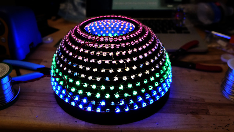
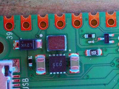
As anyone who has ever assembled a run of PCBs will tell you, quality inspection of solder joints can be a difficult process. Even under a microscope their appearances can be deceptive, and one silver blob can be perfect while its neighbour conceals a problem. The electronics industry have developed inspection tools to help, including optical inspection devices. It’s one of these that [Sina Roughani] has built, in the form of a hemispherical 3D printed dome with concentric rings of coloured LEDs mounted within it.
 The principle behind this tool is as unexpected and simple as it is clever; by having different colours of light from different elevations of the dome it ensures that each different angle of the solder joint surface reflects a different colour. Thus a colour photograph shot from directly above the board allows visual inspection of the quality of the solder joints by the rainbow of colours that appears around their edges. This process can even be automated with OpenCV or similar, hence the process is referred to as Automated Optical Inspection, or AOI.
The technique is demonstrated with some pictures of a Raspberry Pi Pico, on which it shows really well the rainbow-edged solder joints and the red colour reflected from flat pads. What at first might seem like a novelty lighting effect becomes a very useful inspection tool.
PCB inspection is a subject we’ve covered before, though perhaps we don’t all have access to X-rays.


Awesome, I’ve been looking for such project for a while now, but the sweatwork type of job involved is pretty steep.
What about using single pixels led (WS2811 or SK6805) with 1515 or 2020 package, already assembled on a 3 to 4mm strip, then coil on the outside of an helix-dome shape printed part, with tiny aperture for individual leds.
Assembly would be straightforward and one could even control layer/color individually for fake 3D from multiple pictures.
Do you think a straight “stick” of RGB LEDs shining on a PCB on a rotating table and a slow exposure photograph or combined video would have the same effect?
I’m afraid shadows casted by higher parts will reduce the performances.
I think it needs leds with a narrow beam for best result.
Indeed, I explored a NeoPixel solution, but those chips have 120 degree beams, whereas the 5mm LED’s can provide tight, 15 degree beams.
I looked into a strip solution, but the positioning accuracy isn’t great. I actually did a state fair display a few years ago by using acrylic panel light pipes and a NeoPixel strip, but the 5mm’s ended up being cheaper and workable. Another option is a Fresnel lens in front of a monitor with a radial rainbow pattern, but the camera would need to be at an angle and may affect uniformity and repeatability.
You just like paying extra for the WS2811 pixel level programmability that you don’t need in this application. Must be nice to throw money at problems. :P
Last time I paid $1.00 for a total of 100 RGB LED without any extra chips in it. i.e. $0.01 each. Just the usual 3 separate pin to the R, G and B + 1 common power.
Ummm… Was that in the 1990’s? If not please send a link because that means I’ve been overpaying for 5mm LED’s.
today IOs are more expensive than single components anyway, I can’t afford to use 3 pins to drive one LED if I need to drive 100 of them, one DOUT pin is enough for neopixels (:
I think this is pretty clever. You could also use white LEDs and just turn them on and off. Maybe wrap a bunch of WS2812B’s around it and light them individually. Would that give better analysis ability?
I guess I should have refreshed before posting as Tweepy already said it. Great minds? ;)
There is a Technique called RTI imaging largley used for historical artifacts that uses this method http://culturalheritageimaging.org/Technologies/RTI/ With that method, the end result of the capture process is an image you can adjust the lighting on dynamicaly
Excellent!
This takes my eventual stereo microscope goal of having an outer ring or rings (with or without a Fresnel lens cover since not certain how a DIY will perform based on OTC lenses patterns foci) to provide oblique lighting along with the LED rings (UV and I’m thinking Cool or ideally from IR to UV) for direct illumination from above and being the closest inner ring.
I’ll have to read into the AOI dome method some more as I don’t recall ever seeing before.
Wow who wouldn’t want one of those on their bench! I’d turn it on even if I had nothing to inspect.
Print one! If you can’t and at least ten other people are interested, I’ll make them out for about $50. I’m not hoping to profit a lot off of them, I just hope more people can get previously inaccessible cool shots!
Count me in !
No printer… :-( But if you were prepared to ship a print to the UK I’d buy one!
The camera on an SMT pick-and-place machine I use regularly has a somewhat related system. There’s coaxial light, and two levels of ring lights, each with both visible and infrared LEDs. The intensity of each light source and wavelength is adjustable, for each mark or component being detected. This makes it possible to chose an angle, wavelength, and intensity that provides the best contrast for the mark or component, making machine vision far more reliable than with ambient light.
Custom angles, now that’s cool! Back in high school I had an idea for a mechanism to produce a ring of light from a laser similar to what this Australian company is doing. https://precisionlasercleaning.com.au/ I really wanted to advance space travel through space cannons, etc. without doing the actual calculations on minimal energy costs to escape orbit. Even with solar power, it’s about 1k dollars per pound in orbit. The laser would have ionized a ring around the payload for guidance, superheated expansion of the air to reduce drag etc. My solution used a motor with an angled mirror on the shaft to bounce a laser on the same axis to a conical mirror which would divert the light out in a ring pattern. It was just a doodle, I didn’t have the money to build it, let alone patent it, and last year when I saw what this company did, I was kicking myself! I’m glad they’re doing something so neat with it though.
If that sort of design is modified from a conical to a spherical mirror, raising and lowering the motor’s position would steer the cone of light at different angles. This is way more impractical than Dan Gelbart’s solution of laser pointer on a drill chuck. https://www.youtube.com/watch?v=KNweKiuGfJ0
If you wanted to push a 1kW laser into a cone though, you’d need to go with my overengineered solution.
I wonder if this can be used to 3D scan parts.
How do you detect defect with your solution ? I see the picture is nice, but how is it practical?
Yeah, this looks cool but I don’t really understand how it helps find defects?
It helps you see the fillets better. Normally when I do SMT inspection under the scope I need to tilt the board as a scan with my eyes for certain parts to identify if there is a cold solder or anything else. When you inspecting hundreds/thousands of boards they all look the same…except for where the defects are. You take one known good, highly inspected board and feed it through a process with this lighting. Once you have one scan of a known good unit you can run that with something like OpenCV and have it look for differences and flag for further inspection.
I was looking to do a very similar thing after watching that video with the tour of PCBway…they do pretty much the same thing . I am willing to bet that IR and some other freqs might help make things more apparent too.
Thanks for the explanation! I think the prettiness is practical enough. But monkey brains are good at detecting patterns, and even if not automated, this tool can be helpful for manual inspection of solder bridges, etc. Could you explain the IR part? What’s the point aside from ambient light avoidance? With these domes and the newer, 6 inch radius dome I added to the project that doesn’t need to touch the tabletop, they’re bright enough to make ambient light insignificant. You’ll need 500 LED’s from a kit and a lot of soldering but IMO, worth it.
The IR part was something I have been thinking about for a while in regards to photogrammetry and object scanning. I was going to test using an optical pass, structured light and then an IR pass. I haven’t tested it yet but I suspect when you run the IR pass it will give more of a greyscale appearance and may (or may not) make certain features stand out.
In the case of object scanning my plan was to compare the 3 different passes by their point clouds and see if there was any differences.
It may or may not be helpful…just something I was planning on testing at one point and I suspect it may help in this case too. Pretty easy to test though.
Your dome thing really needs to be made to fit a standard stereo microscope mount (if it isn’t already :) ). I think it might work as a light ring replacement/supplement really well…although I am not too sure about the effect of the lighting on your eyes long term…the angled, colored LED light might cause some issues with operators after running for extended periods….but all of that needs more testing for sure.
Overall, I think the project looks good though
Aw. I was planning on doing exactly this, but you beat me to it! A desktop AOI would be awesome. My interest was rekindled a while back after watching one of the strangeparts PCB factory tour videos on YT. Anyway, very cool.
Same here! Strange Parts got me started and I shared it with him through DM. But now you have no excuse not to print it! You can get a reasonably priced LED kit from the eBay sellers selling the 5-color, 100pcs, red green blue yellow white kits for $10, but nobody sells the orange ones in the kits, so you can’t get a rainbow. That’s why I’m considering selling a kit, but if you want one now, just YOLO it. But, don’t buy from the Chinese sellers right now because it’s their New Year holiday right now. Let them enjoy themselves after that bad year.
Nice setup. Let me qualify my comments before I start. I am the Technical director of a company that manufactures AOI for PCB assemblies. This ML (multi light) approach was first patented by Omron in the 90’s (since expired)It is in common use through out 2D aoi systems. it has come good features for solder inspection but some draw backs for other types of inspections. solder profiling with ML gives you a great image of the angles of the solder which would then have to be analyzed by a algorithm.
Simple image comparison is not good enough as solder joints are very variable even when good.
The best part about your design is actually the circular lighting as it allows imaging of the solder at all angles without the issue of getting different image qualities if you used the “stick” type LEDS as you will get a a north-South East-west differences in images also and component that is place at non standard 0-90-180-270 (45 or 60 degrees for example) will have the same image profile as the standard angles.
The main drawback with this type of lighting is shadowing. Taller components next to the item being inspected will affect the image profile. most companies have opted to include “On axis lighting” to combat this effect. The second draw back is actual component inspection. the ML lighting does not give true representation of colour although he human eye can be tricked (RGB pixels on a TV) in to seeing good colour rendition. lighting by RGB will always give a “odd” appearance. again something that is addressed by having an umbrella white light. and take multiple images using each different light sources. these can then be “photoshopped” together to give even more imaging possibilities.