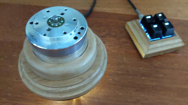
The VHS VCR has now passed from widespread use, and can thus be found as a ready supply of interesting parts for the curious hardware hacker. [Clewsy] has a novel use for a VCR head scanning drum, the part that is supposed to be tasked with reading information off of magnetic tape. Instead, it’s reading information from fingers as the knob for a USB volume control. Underneath the drum is an optical encoder disk which is read by an ATmega32U4 for USB interfacing with a host computer.
 The helical-scan video recorder was a mechanically complex solution to the problem of recording a high-bandwidth video signal onto a tape that could be made slow-moving enough to be practical. By recording the video in diagonal stripes across the tape from a fast-moving spinning head they avoided the need for huge reels of tape, enabling hours of video to be fitted into a roughly book-size cassette.
While over time the mechanics of a VCR mechanism were simplified and cheapened to a great extent, the heads and drum were the one area that could not be compromised. Thus the VCR head was for a time the most high-precision mechanical device owned by most consumers, and the drums usually have exceptionally nice bearings. All of this makes one a particularly good choice for a volume knob or indeed any other large rotational control, so much so that we’re surprised it hasn’t become a more frequent occurrence. So scour the electronic junk, and you might just find the ultimate in free high quality control hardware.
Of course, this isn’t the only thing a VCR head drum can do. How about a centrifuge?


I’ve thought for a long time that it would be great to make a rotary encoder for tuning an SDR with an analog feel out of one of these. But I never got around to it.
I feel like this would make a great paddle input for an arcade machine. I’m sure it’s durable enough.
TEMPEST!
Good instinct – it’s been done and years ago! :) Arcade spinner from VCR parts: http://forum.arcadecontrols.com/index.php?topic=69812.0
Vcr drums use a rotary transformer. There is no direct connection. It has to spin fast and can only transfer a high frequency signal
The transformer is not influenced by the rotation. It must only spin fast to get the video signal bandwidth on the tape.
What a symbol of a whole era of consumer entertainment electronics.
The VCR was like marketing giving engineers an impossible challenge as a joke and then the engineers solving the seemingly impossible.
Some things that may not be obvious:
The pick up heads are directly wired to an air gaped transformer. There is no amplification here it’s a completely passive coupling. This part of the split transformer is in the spinning part of the head and the other half is fixed (not spinning). The signal level here is in the scale you would expect for a passive microphone and the split transformer is operating in a VCR with lots of motors and other forms of electromagnetism. The bandwidth here is better than 5MHz.
The tape path has to be so accurate that it cannot be adjusted by sight.
The tape path (mode) mechanics have to adjust the tape path for several different modes: empty, cassette load, forward wind, reverse wind, forward play, fast forward play, pause, eject.
To record from a TV broadcast signal the spinning head has to be precisely synchronized to line rate of the transmission.
Anyway, I hung up my cotton gloves in the mid 90’s.
Well they were trying to invent home video recording since the 60s, until they finally came up with models that consumers would accept, though early 70s there was a couple of versions you could have found in a high paid techies living room.
What’s also fun to note is that to get the resolution required, you needed a very high tape to head speed. So early attempts tried spooling the tape by quite fast, and you ended up with problems of the tape heating and stretching, and getting eaten by the mechanism easily, and short run times, like half an hour on a tape. So eventually someone got the idea to spin the whole freaking head around (Maybe they watched the exorcist) and stripe frames diagonally on a fatter tape, so as to maintain the head to tape speed, but actually run the tape through at a speed it could survive repeatedly.
Actually 2 inch wide tape and vertical scanning at right angles to tape motion was first. Tape path was warped to the cylindrical section of the spinning head. I saw some of the tape at Radio City in ’59.
Hard constraints always produce the most innovative solutions!
And the biggest mistakes.
I remember one model of VCR that had plastic mode drive mechanics including a planetary reduction drive assembly.
They would come in to my workshop (many of them) with all the plastic gears stripped. I would replace all the stripped gears and as well, the mode switch “just in case”. It was an expensive repair.
Then one day one returned with the same problem after a previous repair. I had repaired it only a month or two prior so I decided to bench test it for quite some time. All went well. And then ….
I was just putting tape after tape in it. I wasn’t bothering to check what tapes I put in it. Then by accident I grabbed a reference alignment tape.
The heads had been cleaned on the previous service so there was no real need to do it again prior to testing. I could do it when I had finished testing. As a rule the reference tape did not go into a VCR unless the heads had been cleaned immediately prior.
I realized this just as I was inserting the tape so I pulled it back out. It had gone far enough it to engage that tape detect switch and the unit started to drive the mode mechanics to load the tape that had been removed.
Then that cringe-worthy sound of all those plastic parts breaking as I am reaching for the power switch.
I had inadvertently reproduces the fault condition.
I examined the unit in great detail even though I was familiar with it and many of the previous models.
The chassis of the deck and the mode mechanics were completely redesigned from the previous model. The electronics was almost identical. However the tape cradle was identical to the previous model.
The tape cradle had a mechanical limit lever. It’s purpose (in the previous model) was to prevent pressure when inserting the tape from causing the mode mechanics to move when the VCR is off. In the previous model, when the VCR was on, the mode mechanics would disable this limit lever. This function was removed from the newer model.
It was a design failure that was fixed with the next model. Essentially, if you briefly inserted a tape and then quickly removed it, the plastic parts of the mode mechanics would self destruct.
After questioning a number of customers who brought these VCRs in with this failure, I discovered that they all had children who used the VCR.
…or a tech who was desperately trying to save a costly alignment tape! The question that has me on the edge of my seat is, did the tape survive?
Yes, the tape survived fine. There is a lot that happens even before the tape is exposed or removed from the cassette.
The secret life of machines video on the VCR is just a joy to watch.
https://www.youtube.com/watch?v=6l18q7Gi4GQ
I used a VCR drum as the basis for a device to calibrate speedometers for restored US WWII military vehicles.
I machined a square end onto a drum shaft extension, which fits the speedo cable input. The drum was spray painted matt black except for a stripe (uncovered after painting by removing adhesive tape) that a cheap Golden Dragon tachometer is pointed at.
A speed-adjustable motor and pinion drives a plastic gear (ordered from Stock Drive Products long ago) fitted to the back of the drum. The motor, drum, speedo clamp, tacho, speed control etc. is mounted horizontally on a wooden baseboard.
So all you used it for was a cylinder? Why not just a piece of cut pipe?
A piece of cut pipe? That would have been considerably more effort to obtain, machine, fit bearings, balance and so on.
I used the VCR drum because it was a) a large, heavy flywheel b) had precision bearings c) had a reflective surface d) was approximately the same diameter as the speedometer and (importantly) e) it was repurposed from a piece of e-waste.
Here is a close-up pic of the device itself, showing the VCR drum. It’s a tad rusty nowadays, and the motor speed control and tacho are no longer on it, but can be quickly restored. The tacho is held down with rubber bands to a piece of wood.
http://www.surfacezero.com/g503/data/4173/WWII_speedometer_calibration_device.jpg
How does it work?
I found no explanation.
Here are some links you might have missed:
https://gitlab.com/clewsy/volcon
https://clews.pro/projects/volcon.php
This reminds me on the car racing arcade game with top down view from the 70s. It had steering wheels for 2 players which you could infinitely rotate in both directions. The rotation of the wheel was directly rotating the car. It was a lot of fun to spin those wheels since the bearings felt almost like those of vcr heads.
Reading the project link above it is made clear that this was an exercise in working with quadrature encoders.
But it does feel like there should be a way to get position information out of a read-head using only the original components.
Were they driven by a brushless motor? Did that have hall sensors?
If not, then it might still be possible to use the back-emf to detect motion, though possibly only above a speed threshold.
What else is in there? Would rhe coupling transformer work as a resolver?