The idea of camless automotive engines has been around for a while but so far has been limited to prototypes and hypercars. [Wesley Kagan] has been working on a DIY version for a while, and successfully converted a Mazda Miata to a camless valve system. See the videos after the break.
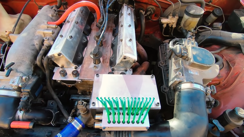
There have been many R&D projects by car manufacturers to eliminate camshafts in order to achieve independent valve timing, but the technology has only seen commercial use on Koenigsegg hypercars. [Wesley] started this adventure on a cheap single cylinder Harbor Freight engine, and proved the basic concept, so he decided to move up to an actual car. He first sourced a junkyard engine head to convert, and use as a drop-in replacement for the head on the complete project car. An off-the-shelf double-acting pneumatic cylinder is mounted over each valve and connected to the valve stem with a custom adaptor. The double-acting cylinder allows the valve to be both opened and closed with air pressure, but [Wesley] still added the light-weight return spring to keep the valve closed if there is any problem with the pneumatic system.
The controller is an Arduino, and it receives a timing signal from a factory crankshaft and operates the pneumatic solenoid valves via MOSFETs. After mounting the new head and control box into the Miata, it took a couple of days of tuning to get the engine running smoothly. Initial tests were done using the compressor in his garage, but this was replaced with a small compressor and air tank mounted in the Miata’s boot for the driving tests.
Although the pneumatic system works well for short test drives, the compressor is quite noisy and adds a couple of points of failure. [Wesley] is also working on a solenoid actuated system, which would require a lot more current from the battery and alternator, but he believes it’s a better long-term solution compared to compressed air. However, he is still struggling to find solenoids with the required specifications.
[Wesley] will be open-sourcing all his designs and code, with the hope that others will be able to modify and improve the design. The results could be very interesting, so we’re hoping a community develops around these camless conversions.


Nice work. It also looks like he have another exciting project in the background!
I find it a bit funny how both videos references Koenigsegg’s Freevalve technology (that they spun off as the company “Free valve”), yet the article doesn’t even mention it.
Since Koenigsegg is a car manufacturer that does actually have camless engines in production. (Though, if one can afford one or even have the patience to wait for one is a different question entirely…)
Going for pure solenoid based actuation is though a bit unpractical, unless one adds on a lever to give the solenoid some more mechanical advantage. But solenoids are honestly not the most power efficient methods of getting mechanical potion to be fair. Though, they are fast at least.
My mechanical knowledge tells me a hydraulic system with solenoids directing the oil flow would probably be best option.
Although a bigger mechanical load on the engine to have a oil pump for that, the solenoids don’t require that much power compared to direct drive ones.
Also run the high pressure oil through a cooler/heat exchanger, and it’ll help cool the solenoids.
Like the Fiat multiair
You probably mean using a solenoid and oil pressure to control the cam timing angle of a, well, camshaft.
Or in some cases, to switch between cam lobes on a camshaft.
This has been done since late 80’s to early 90’s AFAIK, primarily on the intake side, but later also on the exhaust.
Also obligatory “VTEC just kicked in yo”
I find it awfully hard to believe that pneumatics will keep up with high rpms equivalent to mechanical. Air compresses, so it’s a logical NO-GO for high speeds/rps. It would HAVE to be a hydraulic system. Even electric has lag times and would heavily depend on programming.( I wouldn’t use a 10 foot pole to touch someone with a 10 foot pole touching it.
The idea is interesting but it seems like he’s trying to reinvent the wheel.
I believe Free valve works off of an air tank which is charged by cutting fuel to the cylinders, particularly during engine breaking. After all, ICEs are nothing more then air pumps. The added bonus is the air not reserved for the free valve operation can be used to boots intake pressure for an essentially load free turbo charge.
Isn’t the compression a load?
The main reason to go without a cam shaft isn’t to reduce engine load to be fair.
But rather to increase fuel efficiency and power by having better valve timing and faster actuation compared to the cam.
Kind of like HPOP fuel injectors?
Pure solenoid, based valve actuation has been used for decades in diesel trucks and it has been very practical.
“However, he is still struggling to find solenoids with the required specifications.”
If he came to me a couple of years back and asked for advice, I’d have said “you’ll be struggling to find solenoids with the required specifications.”
Best guess for how to implement with obtainable parts would be to use high pressure diesel injectors to drive oil filled hydraulic actuators. What’s that you say? “High pressure diesel injectors are really expensive” yah, coz they’re fast acting high power solenoids.
Although, for this application you can use old diesel injectors, even ones that fail to produce a spray (ie they produce a beam). As long as they still open and close properly they should be fine. You just need to source some beyond repair ones that can’t be used for fuel injection anymore.
OOO…Maybe he could source a mechanical injector and run it off a cam shaft and….wait….
Big part of it is the actual injector part in the tip.
High tolerance machining of some expensive alloys made to be compact and resilient.
Though the “top” coil part is also fairly expensive, but it has nothing on the bottom.
I’m just happy that piezo injectors didn’t take off and they went with “signal inverting” to speed up closing the injectors.
I think he wanted solenoids for direct drive of the valve – a huge power demand.
Solenoid valves for hydraulic actuators are another thing – the power comes from the hydraulic pump. Such valves are in industrial use in a vast amount of variations.
Noob here. How much force is needed to open and close exhaust and inlet valves on an engine?
with or without the standard return spring? (it’s quite beefy actually)
valve itself is 80-120g and needs to move several mm in about 1/8 of the engine cycle…8mm lift @ 3000RPM with a 100g valve would be 256N for linear acceleration (which this is not), so prob more.
– Thinking opening an exhaust valve would have a notable amount of cylinder pressure against it to overcome also…
Did I hear him say he wants to use this system on a rotary engine???
Yup that’s what I heard but I think he might struggle
Yes, and I’m hoping that he was joking.
Exhaust valves on a rotary could be used to curb the unburned fuel loss by having the exhaust cutoff before the tip of the rotor passes the port.
air? so he is recreating Fiat’s Multiair Valve-Lift System?
1) that system uses the engine oil to move the valves
2) it works by hydraulically coupling the tappets and their respective intake valves (exhaust valves are normal), with a small solenoid valve being able to vent said oil, causing the valve to close/stop opening prematurely. It’s not free valves, the Multiair trademark refers to the ability to vary the air charge with each cycle (and theoretically for each individual cylinder).
I think the major issue here is the speed of actuation and how you might want to vary it. The other on the durabily of opening and closing a valve in a hostile environment billions of times. The current mechanical linkage has the benefit of being heat resistant, only mechanical linkages, and being inherently coupled to engine speed. As the piston move faster, intake and exhaust periods stay proportional to valve speed. A replacement system would have to shown to have significant benefits to be viable. The test is not the exotic babbied super car, it is the ill maintained soccer mom minivan. Longevity is the main goal not cutting edge performance which is why auto manufacturers dont put the existing technolgies to the limits except in racing.
Could go full mechanical, run the compressor directly off of the crank. Little bit of custom machining, make it real durable and reliable.
An issue at start-up, though.
Although you could have a small air reservoir to get through the turn-over and up to operating speed, kind of a callback to the way that huge industrial diesels once used compressed air to start, so they had a built-in compressor to fill an air tank for the next cranking.
Also like those big old diesels there would have to be a backup hand pump to build up the charge again if the first one didn’t work. That job probably sucked.
Air started diesel engines is still a thing.
But the “backup hand pump” is these days replaced with a smaller engine, or an electric compressor.
Since most areas that uses air started diesel engines typically have the room for a dedicated compressor, and usually also a generator or two as well.
It is likely though a less fun day when all backup power has gone out. Though for this to happen, one has either left the site neglected/abandoned for a bit too long, or something big as gone wrong and one likely has other issues to contend with.
Some people turn Chevy 350 V8 engines into V6 Air compressors (effectively a 4.3 liter v6 running inside a 5.7 block) by disabling the front two cylinders, inserting check valves in the spark plug holes, and swapping the V8 ignition for a distributor from a 4.3 V6.
A V6 powered air compressor should make more than enough compressed air to run its own pneumatic valves.
Surely it would be easier to convert a V8 to fire on 4 cylinders, can’t quite work out how the crank would allow running on 6 smoothly?
Why not use a supercharger that doesn’t blow to the intake, with a reserve tank for cold starts? Or a turbo (twin?) plumbed in the same way if you don’t want to sap engine power? Although I can imagine that would create quite a bit of unwanted exhaust back-pressure…
I cited the wrong two cylinders being lopped off of the small-block Chevy 5.7 to design the Vortec 4.3 V6.
“The Chevy 90º V6 is formed by the removal of the #3 and #6 cylinders
of a SBC. All three V6 engines share the same 4.4″ bore spacing and
9.025″ deck height of the SBC engine.”
SOURCE:
https://www.crankshaftcoalition.com/wiki/V6_Chevy_90_degree_engines#Blocks
The main problems with using a supercharger are cost and peak pressure. Superchargers cost more than a complete junkyard engine and are only good for a pressure in the ballpark of 6 to 10 psi. For a fast acting solenoid project you would want pressures near the ballpark of 100 psi or more.
Good thing the Miata does not have an interference engine.
Otherwise, debug is going to be noisy.
And brief.
Or maybe not. Maybe without a cam blocking it in from behind the piston would just push a wayward valve up and out of the way. Interesting question.
on modern diesels this would be the case (im in the UK, so by modern diesel i mean 4 valve per cylinder DOHC) as the valves are usually perfectly perpendicular to the piston actuated by rockers with the cams wider than the valves to allow room for the injector bore., so when piston and valve contact the valves are usually actually OK. the rocker arms are almost always smashed to bits. on petrol engines the valves are always (in my experience) canted, so the piston will bend the valve while ramming it home. damage every time.
Rocker arms are sometimes intentionally made brittle, so when you get some hot piston on valves action, the head, piston and cylinder bores will survive.
Sure you’re gonna need new rocker arms and maybe valves if they’re bent a wee bit, but less to replace in case of timing failure.
and if they’re not brittle enough for your liking you can drill a bunch of holes in them and reduce inertia in your valvetrain… though check for oil galleries feeding lifters/dampers etc.
The Miata isn’t an interference engine when set up with its normal cam and timing; if you vary the lift enough you could defs hit piston
Could fuel injectors be used to meter high pressure air?
So in would be an “air injected” and “fuel injected” engine.
You’d still need at least exit valves, but maybe the direct approach would be better than using air to run a piston to open a valve to let air in. I like the idea but I assume it would be a pain to tune.
Maybe you’d get away with a sleeve valve exhaust port though. But getting the air volume is gonna be a problem, it’s hundreds of CFM typical, and you run a 5HP compressor full tilt and get what, like 7? Doing it with a turbo is gonna get you the volume but only pressure up to about 40psi and that’s hard going. Then you need a large bore injector to get that into the cylinder in any amount of time that matters.
Freevalve incorporates AI to “learn” to use different valve timing and thermodynamic cycles in different conditions all on its own. As cool as it will be to mimic the mechanical function of a camless valve train, that is a far cry from achieving what Freevalve is on the verge of accomplishing.
Well, why not get rid of crankshaft all together and turn it into linear generator?
I’ve wondered about this for years. Glad to see someone trying it.
A Miata makes an ideal lab rat here because it has a non-interference engine. On many engines, if a valve is open at the wrong time, it can get whacked by the piston and that’s all-she-wrote. On a non-interference engine, valves and pistons move in wholly separate spaces, i.e. their motions don’t overlap. Poor timing of may prevent ignition (or uglier symptoms) but it won’t smash metal against metal.
I wouldn’t mind slappin that thing on a short box chevy frame with planetaries and 44’s. ( throw some skinny tall mud cutters on the back)
Prior art:
https://hackaday.com/2009/06/24/evic-engine/
To get around the issue of not finding appropriate solenoid valves, could multiple solenoids for each valve be a solution? Either multiple solenoids working together to actuate one valve, or multiple solenoid valves “Tee-ing” together at the head?
Or I guess you could stop trying to find compact ones, put a 90 degree crank horn on top of the rockers, and have two beefy buggers in a push pull mounted horizontally across the top of the engine bay. (BTW if you’re smart you dump the EMF out of one into the other)
ever heard about 2 stroke?
Amen dude.
Why not just go to a opposed piston, and do away with the cam the easy way. Their economical as well. There’s a company doin just this for the trucking industry, and also built one for a ford truck.
Renault might have done it if not for the FIA regs
http://www.formula1-dictionary.net/pneumatic_valve_actuation.html
I applaud your enthusiasm and ingenuity. But…..you couldn’t find a vehicle with a simpler engine? Just to prove concept? You probly had a lot of fun dinking with the miata, and it was interesting to watch.
There was a push in the 1990s for 48V automotive electrics, partly to facilitate such features as electrically-operated cams and other high electrical loads like electric superchargers. I don’t think idea tool off, probably due to the massive existing base of 12V systems. https://en.m.wikipedia.org/wiki/42-volt_electrical_system
Me: open mouth-insert foot.
I should have watched part one before part 2
Solenoids can be managed with capacitive discharge, for high impulse current.
Big 2 strokes use hydraulics (still from a camshaft mind) to open the valve and an air spring to close it again. As someone said earlier 2 strokes is where the gains are to be made!