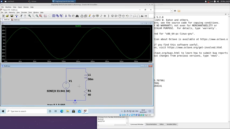
[Ted] recently demonstrated the analysis of an RL circuit using a piece of paper, Octave, and LTSpice. If you prefer, the Octave code should work fine in MATLAB, as well. If you are looking to get serious about electronic theory this is a reasonably simple case and is a good chance to get a workout with some of the tools.
We like the approach because too often it is easy to just use the computer and not pick up the understanding that you get when working through a problem by hand. You do need to understand complex numbers, but, overall, the math isn’t too hairy.
In real life, you’d be unlikely to use all of the tools [Ted] shows. However, each has its place. Working something out by hand can help understand and problem solve. Octave is great if you are trying to code a simulation. But for hands-on practical use, LTSpice is an excellent tool. The price is right, too.
There are many ways to work through an AC circuit, but phasors have the virtue of making the math relatively simple. The less time you are spending calculating, the more time you can spend understanding the circuit’s behavior. Of course, with the simulation tools, you can spend zero time on the math, if that’s what works best for you.
Of course, there are other simulators we like, too. There’s the one we like to run in the browser. Or, download Micro-Cap 12 which is also free to use.


Would have been nice if the article had a sentence or two explaining what a phasor is. It’s my understanding that good articles do such things.
I believe it’s the Deus Ex Machina available to Star Trek writters for away teams. When the difflector array isn’t available.
Let’s see the photon tomatoes modeled in MATLAB.
it’s a number that represents a magnitude and angle. Say the input of a circuit is a sine wave of 1Volt and we arbitrarily assert that it’s the reference phase ( 0 degrees ). The output of the circuit , if it’s a linear circuit , will be a sine wave with a magnitude and a shift relative to the original signal. For instance it might be 0.7 Volt and delayed 30 degrees. Then the output is a phasor with 0.7 magnitude and -30 degrees angle.
A circuit vector? Cool.
Jokes aside I think there is a subtle difference in that they are actually complex functions in polar notation.
(Complex numbers also being very vector like). Its not that you can’t think of it as a vector it’s just that thinking of them as something else is more useful.
I can’t recall what the term is… google says “analytic signal” but that rings literally no bells…
“Phase Vector”, hence the portmanteau “phasor”.
It is used to represent voltages and currents in a single-frequency system as a complex number, where the absolute value of the number is the amplitude, and the argument of the number is the phase of the signal in question.
Hahaha love the title havent even rtfa yet. Kudos :)