Lorenz Attractor Analog Computer With Octave Simulation

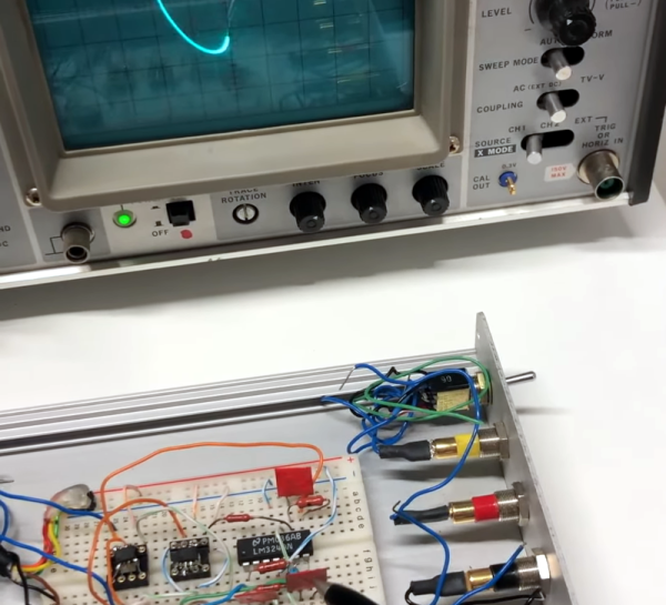
[Janis Alnis] wanted to build an analog computer circuit and bought some multiplier chips. The first attempt used apparently fake chips that were prone to overheating. He was able to get it to work and also walked through some Octave (a system similar to Matlab) simulations for the circuit. You can follow along in the video below.

Getting the little multiplier chips into the breadboard was a bit of a challenge. Of course, there are a variety of ways to solve that problem. The circuit in question is from the always interesting [Glen’s Stuff] website.

From that site:

The Lorenz system, originally discovered by American mathematician and meteorologist, Edward Norton Lorenz, is a system that exhibits continuous-time chaos and is described by three coupled, ordinary differential equations.

So, the circuit is an analog solution to the system of differential equations. Not bad for a handful of chips and some discrete components on a breadboard. We’ve seen a similar circuit on Hackaday.io.

Check out our recent competition winners if you want to see op amps do their thing. Analog computers were a thing. They aren’t always that complicated, either.

Continue reading “Lorenz Attractor Analog Computer With Octave Simulation”

This Found-Sound Organ Was Made With Python And A Laser Cutter

Some readers will no doubt remember attaching a playing card to the front fork of their bicycle so that the spokes flapped the card as the wheel rotated. It was supposed to sound like a motorcycle, which it didn’t, but it was good, clean fun with the bonus of making us even more annoying to the neighborhood retirees than the normal baseline, which was already pretty high.

[Garett Morrison]’s “Click Wheel Organ” works on much the same principle as a card in the spokes, only with far more wheels, and with much more musicality. The organ consists of a separate toothed wheel for each note, all turning on a common shaft. Each wheel is laser-cut from thin plywood, with a series of fine teeth on its outer circumference. The number of teeth, as calculated by a Python script, determines the pitch of the sound made when a thin reed is pressed against the spinning wheel. Since the ratio of teeth between the wheels is fixed, all the notes stay in tune relative to each other, as long as the speed of the wheels stays constant.

The proof-of-concept in the video below shows that speed control isn’t quite there yet — playing multiple notes at the same time seems to increase drag enough to slow the wheels down and lower the pitch for all the notes. There appears to be a photointerrupter on the wheel shaft to monitor speed, so we’d imagine a PID loop to control motor speed might help. That and a bigger motor that won’t bog down as easily. As for the sound, we’ll just say that it certainly is unique — and, that it seems like something [Nicolas Bras] would really dig.

Continue reading “This Found-Sound Organ Was Made With Python And A Laser Cutter”

MicroSynth, the business card-sized synthesizer

MicroSynth Mixes All-Analog Fun With A Little Business

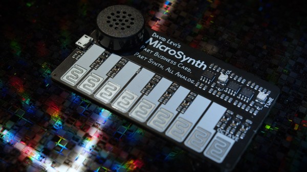
While [MicroKits]’ MicroSynth is an all-analog synthesizer that fits on a business card-sized PCB, and he actually does use it to break the ice in business meetings, that’s not really the idea behind this project. Rather, [MicroKits] is keen to get people playing with synths, and what better way than a synth you can build yourself?

There was an ulterior motive behind this project, too: prototyping circuits for a more complete synthesizer. Thus, the design is purposely very simple — no microcontrollers, no logic chips, and not even a 555 to be found. It doesn’t even have buttons; instead, the one-octave keyboard just has interdigitated traces that are bridged by the player’s fingers, forming resistive touchpads. The keyboard interface circuit is clever, too — [MicroKits] uses a pair of op-amps to convert the linear change in resistance across the keyboard to a nearly exponential voltage to drive the synth’s voltage-controlled oscillator (VCO). The video below shows what it can do.

We love projects like these because they show what can be accomplished strictly using analog circuits. We don’t have any problem with other synth designs, mind you — this 555-based dub siren we featured recently was great, too. Continue reading “MicroSynth Mixes All-Analog Fun With A Little Business”

Phasors In LTSpice

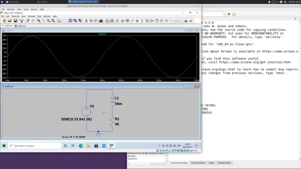
[Ted] recently demonstrated the analysis of an RL circuit using a piece of paper, Octave, and LTSpice. If you prefer, the Octave code should work fine in MATLAB, as well. If you are looking to get serious about electronic theory this is a reasonably simple case and is a good chance to get a workout with some of the tools.

We like the approach because too often it is easy to just use the computer and not pick up the understanding that you get when working through a problem by hand. You do need to understand complex numbers, but, overall, the math isn’t too hairy.

Continue reading “Phasors In LTSpice”

Tutorial On Signal Processing In Linux With Octave

If you’ve taken any digital signal processing classes at a college or university, you’ve probably been exposed to MATLAB. However, if you want to do your own work, you might think about Linux and one of the many scientific computing applications available for it.

[David Duarte] recently published a three-part tutorial on using Octave to do scientific audio processing. The first part covers basic reading, writing, and playing of audio files. Part two covers synthesis of signals, plotting, and some basic transformations.  Modulation is the topic of the third part. If you prefer your tutorials on video, you can check out the video below.

We’ve talked about MATLAB before in the context of message cracking. Then again, some of the best signal processing is done by humans. If you don’t like Octave, you might try Scilab, another Linux package that is similar. There’s also Freemat, Sage, and Spyder. Of course, you can also run MATLAB under Linux.

Analog Test Interface For Your Computer

Wanting to test the response curves on some analog parts, [Don Sauer] devised a way of using simple tools to graph analog tests on a computer. Here you can see the results of testing NPN, PNP, NMOS and PMOS transistors, but modifying the input circuitry would let you test just about anything you want.

[Don] is using an Arduino as the hardware interface. He needed some additional parts, like an op-amp and some passives. Instead of building this on a breadboard, he printed the circuit out on a piece of cardboard, hot glued the components in place, then wired them up. This will let him reuse the interface in the future, but is quicker than designing and etching a PCB.

He uses a Processing sketch to capture the test data streaming in from the Arduino. Once recorded, he uses SciLab to create the graphs. He also covers a method of sifting through the data using Octave, another open source program that feels somewhat like MATLAB.