Anyone who’s ever tried their hand at reverse engineering a piece of hardware has wished there was some kind of magic wand you could tap on a PCB to understand what its doing and why. We imagine that’s what put security researcher [Mark C] on the path to developing CurrentSense-TinyML, a fascinating proof of concept that uses machine learning and sensitive current measurements to try and determine what a microcontroller is up to.
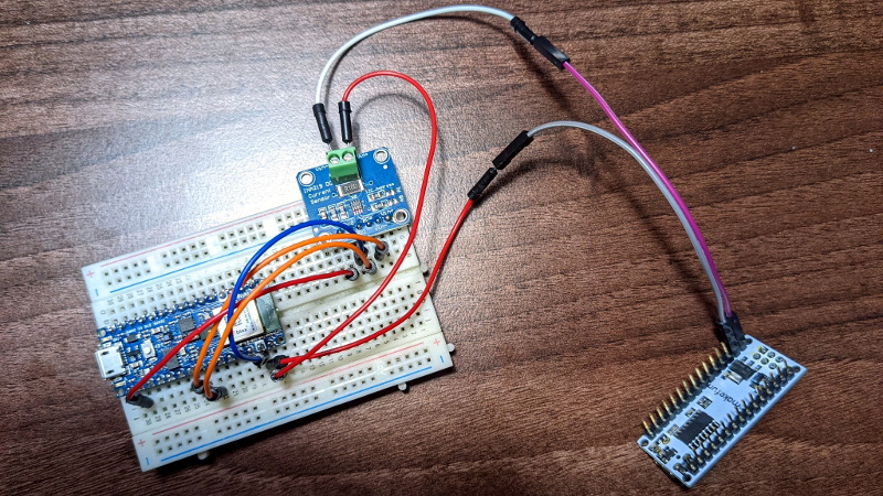
The idea is simple enough: just place a INA219 current sensor between the power supply and the microcontroller under observation, and record the resulting measurements as it goes about its business. Of course in this case, [Mark] knew what the target Arduino Nano was doing because he wrote the code that blinks its onboard LED.
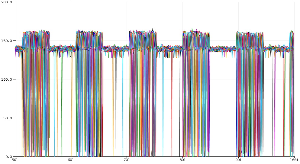
This allowed him to create training data for TensorFlow, which was ultimately optimized into a model that could fit onto the Arduino Nano 33 BLE Sense which stands in for our magic wand. The end result is that the model can accurately predict when the Nano has fired up its LED based on the amount of power it’s using. [Mark] has done a fantastic job of documenting the whole process, which also doubles as a great intro for putting machine learning to work on a microcontroller.
Now we already know what you’re thinking: obviously the current would go up when the LED was lit, so the machine learning aspect is completely unnecessary. That may be true in this limited context, but remember, this is just a proof of concept to base further work on. In the future, with more training data, this technique could potentially be used to identify a whole range of nuanced activities. You’d be able to see when the MCU was sitting idle, when it was writing to flash, or when it was reading from sensors. In fact, with a good enough model, it might even be possible to identify the individual sensors that are being polled.
These are early days, but we’re very interested in seeing where this research goes. It might not be magic, but if analyzing the current draw of a coffee maker can tell you how much everyone in the office is drinking, then maybe it can help us figure out what all these unlabeled ICs are doing.


This is great if you don’t know how things are memory mapped in the chip. Dumping the firmware is still you’re best bet for figuring out what is being executing because even if you can tell which instructions are being executed, you cannot tell what their exact parameters are.
Great comment. Wish I was cool enough to do a firmware dump and analyze contents. Too many hobbies already. Cool tech though. Thanks all.
“The idea is simple enough: just place a INA219 current sensor between the power supply and the microcontroller under observation, and record the resulting measurements as it goes about its business.”
Kind of the electrical panel monitors writ small. See what all the devices in one’s house are up to.
This is a good framework for a more general tool – power monitor for hardware debugging. I use a simple panel meter to do this without logging. I created a USB backpack for those cheap “5 digit ammeters” – https://www.grbl.org/single-post/panel-meters. It really helps to see what’s going on when you are testing a new project.
A great addition would be a current limit switch like the TPS25221. This would allow you to set a cut off limit to avoid releasing blue smoke.
Using I2C current monitor to power analyze multi-MHz micro is plain stupid.
So, actually, it isn’t stupid, but let me clarify – we’re not talking full AES key recovery here… for full side channel attacks on modern uC’s, the usual recommendation is about 100MS/s (Colin O’Flynn has tested that), but Alyssa Milburn (@noopwafel) showed that you can still do CPA key recovery on AES using an XMEGA chip (cf. her HorrorScope).
The INA219 supports High Speed mode for I2C (as I’m sure you read in the jupyter notebook) so whilst I don’t think this can do key recovery, it has a high likelihood of being able to do some functional analysis on a blind firmware with the right processing (ML or otherwise).
Lastly, we’re not monitoring a multi-MHz micro. We’re monitoring an LED. Cheers, M.
Mark C said: “The INA219 supports High Speed mode for I2C (as I’m sure you read in the jupyter notebook) so whilst I don’t think this can do key recovery, it has a high likelihood of being able to do some functional analysis on a blind firmware with the right processing (ML or otherwise).”
High speed I2C doesn’t matter. What limits the information rate you can obtain from the INA219 is the frequency response of the chip, around 1 KHz at -3 dB (see datasheet Fig.,-5), and the depth setting of the moving-average filter (e.g. 128 samples). If you want to monitor true microcontroller current or energy consumption in the time domain in a meaningful way, the INA219 is the wrong tool. Use a fairly high bandwdth (5 to 10 times the microcontroller’s system clock frequency) Digital Storage Oscilloscope (DSO) with plenty of sample memory and internal math functions. Put the DSO across a non-reactive shunt resistor.
Yes I know (side channel attacks are part of my day job) – but that’s not the point :P M.