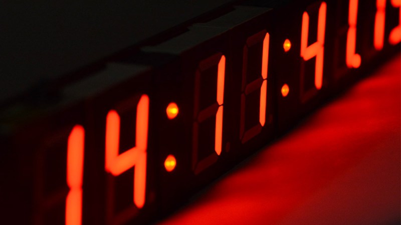
This is a story about a successful system that nevertheless failed to make the cut. An experimental LED brightness adjustment is something [Mitxela] explored in a project for a high-precision clock; one that shows time down to the nearest millisecond, and won’t flicker or otherwise look weird when photographed with a high-speed camera. To pull this off means reinventing many things about a clock display, including how to handle brightness adjustment elegantly. Now, to be clear, the brightness adjustment idea described here is something that did not end up being used, but it’s interesting enough that [Mitxela] wrote it up and we’re very glad he did.
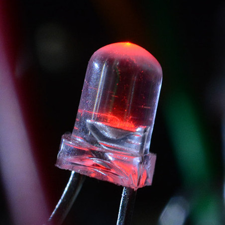 The idea was to have a smooth and seamless automatic brightness adjustment, ideally with no added components. Since LEDs can be used as light sensors, [Mitxela] saw an opportunity to use elements of the clock displays themselves as sensors. This is how it works: a charge in the p-n junction that makes up an LED will decay at a rate proportional to the amount of light hitting the junction. By measuring the speed of this decay, it’s therefore possible to tell how much light is hitting the LED. It’s effective and elegant, but there are a few practical issues to deal with.
The first failed idea was to employ as sensors the unused decimal points in the seven-segment LED modules, but that turned out to have issues. One was the common-cathode wiring of the display modules; this makes them very convenient to drive as displays, but made using the decimal point as a light sensor impractical. The other issue was that the built-in diffuser that makes the displays easier to read absorbs a lot of ambient light. A much better option was to use the LEDs in the colon separators between digits, since they’re independent. Naturally they still have to light up in addition to being used as sensors, but [Mitxela] made a successful prototype by performing the necessary measurements in between the LEDs being driven by PWM.
Despite how clever and efficient the solution was, in the end what sank it was the fact that the LEDs just don’t do a very good job of sensing ambient light for this purpose. The LEDs are simply too directional. Even after sanding away the top (lens) part of the LEDs, they still had a very narrow field of view. As [Mitxela] describes it, tilting the clock towards the ceiling could send it to full brightness, and the shadow of one’s head falling across the clock would plummet it into “night mode” dimness. In short, it responded to what was directly in front of it, rather than the ambient light level as a whole.
It’s a reminder that sometimes a solution simply won’t tick all the right boxes, and it can happen for unexpected reasons. Still, LEDs are versatile things. Not only can they sense light, but as the name implies they’re also diodes. As diodes can be used as temperature sensors that means LEDs can as well.


Oh and LED can also serve as “varicap” diodes as well, thanks to their large/wide junction.
The problem is that LED have much lower reverse voltage rating – around 5V, which doesn’t give you much range to work with.
5 V is an oft-quoted number, but have you actually measured it?
I have. Independent of color or type, any modern LED out of the dozens I’ve tested have been more than 24 V.
I recall working at of the Burstein-Applebee store’s electronics counters back in he mid 70’s when I saw a Sams book by Forrest Mimms III on optical communications. He used LEDs bidirectionally as both a transmitter and receiver (no solid state lasers were around, or at least common-place back then). Int the early 70s he showed his idea to AT&T then in 1978, teams of lawyers descended on his home in Texas claiming patent infringement. Google “AT&T sues forrest mims”.
https://hackaday.com/2017/01/18/forrest-mims-radio-shack-and-the-notebooks-that-launched-a-thousand-careers/
I am using a red LED, ten turn trimpot and bc548 as a voltage regulator on a ZN414 / derivative MF receiver currently. Quantum mechanics ftw!
It’s funny how things come back around. The two I/O pin bidirectional LED trick was specifically created to allow a remote control keyboard back light LED to serve as its own sensor.
https://www.merl.com/publications/TR2003-35
Of course, in that case it was used to turn on the LED when it was dark as opposed to dimming in darkness.
I suppose, if it’s a white LED, the phosphor might glow long enough for the diode to detect its own light output.
Several years ago I measured the decay time constant of white LED phosphor, in the course of building a high speed (1 us) high power (10 kW) LED strobe. It’s 1-2 microseconds, depending on color: the two components of the phosphor (red, yellow) decay at different rates. The blue exciter LED decayed at the rate of the electrical waveform (<0.1us), and is likely much less than that.
BTW: a high-speed (sub-microsecond LED strobe is a dumb idea. BOM cost per light output is very high for microsecond-scale pulses. Overdriving the LED doesn't help: you can't get more than 10x the steady-state light output before it toasts, and the efficiency goes WAY down: poorer than an air-gap flash. Much quieter though :-)
Paul, I’d love to hear more about the LED strobe research you did, ia it written up anywhere?
Ha. A 7 year old abandoned project — Whatever writeup existed is lost to bitrot. The most info available online is probably in my comments to a previous HaD article: https://hackaday.com/2019/05/16/an-impeccably-designed-high-speed-led-flash/
Thanks Paul!
And that scheme (measuring its own light) won’t work: the blue LED acting as a sensor is completely blind to the yellow & red produced by the phosphors.
A bare blue LED can see its own reflection though.
Maybe it’s adjusting the brightness too aggressively? Brightness adjustment is mostly only useful when coming from dim to bright (i.e. you woke up at night, and you turned on the lights from your nightstand). Coming from bright to dim, should have a bit of delay since your eyes probably wouldn’t adjust to darkness that fast, as compared to the opposite.
Then again, this wouldn’t solve the “narrowness” of the LED as a sensor, but it should help mitigate the effects of it, by a bit if you ask me.
LED’s are great for detecting bright flashes – like large arcs in the lab. A neat solution is to mount one in a BNC socket and plug it right into the scope. More sketchy is poke the pins into the socket on the scope. Doesn’t matter which type used. Arcs tend to be bright and fairly wide in optical frequency output.
Has anybody ever tried to make a sort of ccd sensor out of a matrix of leds? It would be a funny experiment, although pretty useless…