In a world with software-defined radios and single-chip receivers, a superheterodyne shortwave radio might not exactly score high on the pizzazz scale. After all, people have been mixing, filtering, and demodulating RF signals for more than a century now, and the circuits that do the job best are pretty well characterized. But building the same receiver using none of the traditional superhet trappings? Now that’s something new.
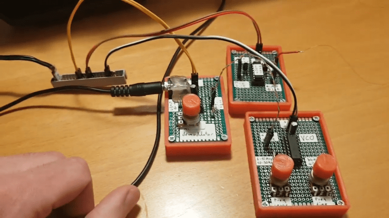
In what [Micha] half-jokingly calls a “74xx-Defined Radio”, easily obtained discrete logic chips, along with some op-amps and a handful of simple components, take the place of the tuned LC circuits and ganged variable capacitors that grace a typical superhet receiver. [Micha] started by building an RF mixer out of a 74HC4051 analog multiplexer, which with the help of a 2N3904 phase splitter forms a switching mixer. The local oscillator relies on the voltage-controlled oscillator (VCO) in a 74HC4046 PLL, a chip that we’ve seen before in [Elliot Williams]’ excellent “Logic Noise” series. The IF filter is a simple op-amp bandpass filter; the demodulator features an op-amp too, set up as an active half-wave rectifier. No coils to wind, no capacitors to tune, no diodes with mysterious properties — and judging by the video below, it works pretty well.
It may not be the most conventional way to tune in the shortwave bands, but we always love the results of projects that are artificially constrained like this one. Hats off to [Micha] for the interesting trip down the design road less travelled.


Few decades ago it was illegal to listen to abroad radio in my country. Radio receivers on the market were restricted to local bands. It was even illegal to posses parts needed to build such unrestricted radio. I wonder if one can make radio receiver from parts scavenged from CFL lightbulb. Because nowadays you can find them everywhere. On the other hand, nowadays twitter seems to be more relevant in event of civil war.
Woah, which country was that? I have not heard of such a thing.
CZ = Czechoslovakia.
Czechia [01-Jan-1993 to present. The official short form name of the Czech Republic.]
Czech Republic [01-Jan-1993 to present. Multi-Party Parliamentary Representative Democracy. Relatively free and prosperous. 2020 per capita PPP GDP $40,585.]
Czechoslovakia [1918-1993]
Czech Socialist Republic [1969–1990. USSR controlled. Socialism, lots of intimidation & censorship.]
Protectorate of Bohemia and Moravia [1939–1945. Nazi Germany controlled. Arguably worse than being controlled by Socialism.]
>Arguably worse than being controlled by Socialism
Both were expressions of real socialism – the only difference being whether you divide the people according to race or by class.
If one looks at Socialisem – however here thw word is used for Communism – and all the countries like Russia and China were all non-democratic countries before – during and after changing thier political form. Socialism is not about being undemocratic but a form of spreading money around….Communism seem to be much more restrictive – no private enterprise at all.
It was der Protektorat Böhmen und Mähren; the former (and nowadays too) Czech Republic, during German occupation between 1939 and 1945.
Twitter might not be what you think it is. Definitely would not rely on it in daily life, especially not a time of war.
Wouldnt be too hard if had just a few caps, wire, and a couple transistors. Just build a regenerative radio . A good one would have a single transistor as an input preamp before the regen so it wouldnt leak out too much rf out the antenna connection.
In all likelihood, any homebrew or modified commercial receiver would be illegal, since the components required to change frequency are completely generic and can be scavenged from almost any electronic device. We’re talking about inductors that can be made from a scrap of wire. How is THAT enforceable??
They’ve killed people for their race or sexuality… I mean… If they could figure our you’re gay, they could’ve figured out you’ve transistors and coils hidden under your pillow.
In Ham Radio magazine about 1974, someone described a TTL based SSB transceiver IF strip. Obviously the gates were linearized. And no balanced modulator, so the crystal filter had to get rid of the carrier.
I don’t think there’s even a specification for how well the carrier has to be suppressed in a SSB transmitter. Sure, “spurious” signals have to be under -50 dBc, but if you just call it “reduced sideband” rather than “single sideband”, it’s not a spurious signal.
If there is residual carrier getting through the IF on the receiver side, there could be a beat between the second mixer and the carrier, but it should be at a low enough frequency for the audio amplifier to reject it. The actual benefit of SSB is that you don’t have to waste a lot of power transmitting the carrier, and even 10 dB of carrier rejection is enough to get practically all of the benefit of that. So really, not a big deal.
On the other hand, double balanced mixers are generally less lossy than unbalanced designs, resulting in a higher signal to noise ratio and therefore higher effective sensitivity.
Michael, Your mention of that TTL SSB transceiver brought back some memories from reading a lot of ham radio magazines way back a long time ago in a world that did not have the internet. I faintly remember reading exactly what you mentioned. I think the article you are referring to was published in “Ham Radio Magazine” in November 1975 on page 18 – called “using TTL ICs in single-sideband equipment’. It is a description of a complete transceiver using only 3 SN7400 NAND gates. Thanks for bringing it to my attention – and causing me to track it down. I’ve hit the print button on the article and will be giving it a read (again). — Setho
The article is available on the web at: https://archive.org/details/hamradiomag/ham_radio_magazine/Ham%20Radio%20Magazine%201975/11%20November%201975/page/n19/mode/2up
Oh great, there goes untold hours of reading and downloading old articles. But seriously thanks for the link.
So tempting to make a MHz 555 out of 7486’s in linear mode.
I find it really interesting that it took so long for what is now called SDR to emerge as a useful technology. When I think of the past I think of all the work on continuous multiplication of signals using the non-linearities of tubes and semiconductors to make “mixers”. The oldest paper I have seen on using a chopper is maybe from the late 1980’s? From Stanford? It had all the ideas needed for modern SDR but did not put them together.
Someone realized the way to multiply a signal by a sin (and a cosine for quadrature) is to multiply it by a square wave since the square wave is made of all the odd harmonics of its fundamental frequency. But multiplying by a square wave is the same as turning the signal on and off. And shazam!, all the complicated circuitry is gone in a flash. Just filter.
IIRC 4000U series and 74C04 (not HC) can be used in a linear mode like simple op-amps. I wonder if a 74C00 can be made to chop an analog signal? It would be simpler than the multiplexer.
A great project that would complement SDR is a scratch built Delta/Sigma ADC done mostly in software with an ATMega328 like a Nano. I would love to see the software for that.
You make some good points there. Just one thing: a delta/sigma ADC has one serious drawback: it has a noise level that increases with frequency. This happened to not be a problem when consumer electronics makers started using them on CD players, because human hearing sensitivity drops off at high frequencies faster than the noise level of a delta/sigma increases, but where you’re processing the data digitally this is going to be an issue.
I’m sure that a 74C04, or more to the point, a 4011, COULD be used to chop a signal, but really, this is already a solved problem with the CMOS analog switches. How do you figure that a NAND gate would be simpler than an analog multiplexer?
I was thinking a delta/sigma at very low frequency. It fits well with SDR in that you get a lot for what seems like practically nothing. Square wave chopper plus software in one case, a 1 bit ADC plus software in the other.
You can get 7400 parts in tiny packages these days with only 1 or 2 elements I think, like a 4 pin surface mount. I see analog switches in the very small packages. How fast is he switching in this project? I think these would top out at around 20MHz https://www.maximintegrated.com/en/products/analog/analog-switches-multiplexers/MAX4688.html
The concept of switching mixers is very old. Ring modulators (with metal rectifiers) can be found in professional gear from the 1920s. Later, beam deflection tubes were developed, the commercial type 6AR8 was used as chroma detector in color TVs.
Chop till your harts content.
XOR (A) => linear input
Output (Q) though a low pass RC filter ie output (Q) trough resistor to input (B), capacitor from input (B) to ground.
this will hold the (A) input within the linear range and chop at the same time.
Usually, an XOR gate has different propagation delays for rising and falling edges, which is less of a problem with analog multiplexers, but yeah, a fast enough XOR gate should do the job.
“I find it really interesting that it took so long for what is now called SDR to emerge as a useful technology”
Yeah, but people are still not realizing how well tube technology and SDRs actually do play together.. Instead they continue thinking in black and white. *sigh* Tubes are well designed for RF input stage of a radio, for example, because tubes do have an excellent large signal immunity. And can survive EMPs. If overloaded, they slowly go into saturation. Tranistors are so primitive, by comparison. The tube’s closest relative, the field effect transistor, is very sensitive to static and high charges. Man, if only the Nuvistor was further developed.. *sigh*
Anti-parallel diode pairs across receiver input (and a fuse in series for good measure) are transistor receivers’ friends. Plus/minus 0.6V amplitude signal is already way more than what a receiver which is not a passive crystal/diode detector is needed for.
I like this design a lot.
1) I’ve never seen a phase splitter used in an RF front end, but this does simplify things a lot – most double-balanced mixers require two toroidal transformers, and toroids are the most expensive parts in a cheap radio. The phase splitter costs one transistor and does away with the toroids. I see 4051s for $0.11 (which is cheaper than I can get a single torid for!), and 4046s for about $0.21, so this can be an extremely cheap receiver.
2) A switching mixer should have practically 100% efficiency, since there is very little time when neither phase of the signal is being used. This does mean that it will also receive on odd harmonics of the LO, though, so when tuned for 7 MHz, it will hear 21 MHz almost as well.
3) Using an op-amp for a detector is also pretty nice from a sensitivity standpoint, and also eliminates the need to bias the diode, since the op-amp will do that automatically.
4) My biggest pet peeve about electronics is how much KNOBS cost. Hooray for 3D printing!
Amen! :D
Look up the Tayloe Detector circuit. He used a 74HC4053 1:4 multiplexer chips for a very high dynamic range IQ mixer. The advantage is that you can build a local oscillator at four times the frequency of interest. This makes SSB direct conversion receivers relatively straightforward.
@Jake Brodsky, AB3A said:”Look up the Tayloe Detector circuit.”
There are convincing arguments Tayloe did not invent that detector. For example one term used in prior art is DCQSD (Direct Conversion Quadrature Synchronous Detector), there are others.
These are quadrature detectors (or down converters) that when used with DSP (e.g. the Hilbert Transform[1-2]) or a hardware phasing network will receive or transmit SSB or CW signals. The design is functionally symmetrical, it will receive or transmit. A key thing to know about these detectors is that the gain and bandwidth depend on the antenna impedance, so if you design for 50+j0 you better feed it with a well matched antenna. See pp-19 & 20 of [3] for more on this. Also, these detectors are notorious for RF leakage at the antenna port if the mixer is unbalanced.
A seminal series of four articles on these devices is: “A Software-Defined Radio for the Masses by Gerald Youngblood, AC5OG”[3-6].
* References:
1. Single-Sideband Modulation – Mathematical Formulation
https://en.wikipedia.org/wiki/Single-sideband_modulation#Mathematical_formulation
2. Hilbert Transform – Single Sideband Modulation (SSB)
https://en.wikipedia.org/wiki/Hilbert_transform#Single_sideband_modulation_(SSB)
3. A Software-Defined Radio for the Masses by Gerald Youngblood, AC5OG. Part-1 QEX Jul/Aug 2002, pp. 13-21
http://www.arrl.org/files/file/Technology/tis/info/pdf/020708qex013.pdf
4. A Software-Defined Radio for the Masses by Gerald Youngblood, AC5OG. Part-2 QEX Sep/Oct 2002, pp. 10-18
http://www.arrl.org/files/file/Technology/tis/info/pdf/020910qex010.pdf
5. A Software-Defined Radio for the Masses by Gerald Youngblood, AC5OG. Part-3 QEX, Nov/Dec 2002, pp. 27-36
http://www.arrl.org/files/file/Technology/tis/info/pdf/021112qex027.pdf
6. A Software-Defined Radio for the Masses by Gerald Youngblood, AC5OG. Part-4 QEX, Mar/Apr 2003, pp. 20-31
http://www.arrl.org/files/file/Technology/tis/info/pdf/030304qex020.pdf
THis 555 will go up to 90MHz so – coulda used that as the LO…
https://hackaday.com/2019/03/25/the-worlds-fastest-555-timer-and-the-state-of-the-555/
I love your simple and elegant design. I’ve seen in the 70s a stereo multiplex generator using ttls. As for myself I made a tiny am modulator, using an attiny with 1khz pwm output, and a hcttl gate fed by a dds generator. This is useful for radio calibration. This schema is far more simple than using an analog balanced modulator
http://rf-circuit-schematic.blogspot.com/2011/03/cd4066-fm-stereo-encoder.html
Djenta mice shawing communist