Minimal Mods Make Commodity LNBs Work For QO-100 Reception

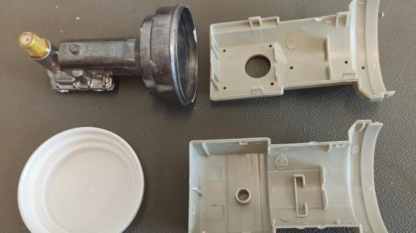
A word of advice: If you see an old direct satellite TV dish put out to the curb, grab it before the trash collector does. Like microwave ovens, satellite dishes are an e-waste wonderland, and just throwing them away before taking out the good stuff would be a shame. And with dishes, the good stuff basically amounts to the bit at the end of the arm that contains the feedhorn and low-noise block downconverter (LNB).

But what does one do with such a thing once it’s harvested? Lots of stuff, including modifying it for use with the QO-100 geosynchronous satellite (German link). That’s what [Sebastian Westerhold] and [Celin Matlinski] did with a commodity LNB, although it seems more like something scored on the cheap from one of the usual sources rather than picking through trash. Either way, these LNBs are highly integrated devices that at built specifically for satellite TV use, but with just a little persuasion can be nudged into the K-band to receive the downlink signals from hams using QO-100 as a repeater.

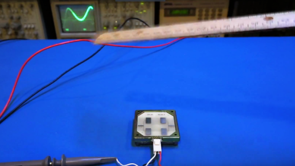
The mods are simple — snipping out the 25 MHz reference crystal on the LNB board and replacing it with a simple LC bandpass filter. This allows the local oscillator on the LNB to be referenced to an external signal generator; when fed with a 25.78 MHz signal, it’s enough to goose the LNB up to 10,490 MHz — right about the downlink frequency. [Sebastian] and [Celin] tested the mods and found that it was easily able to detect the third harmonics of a 3.5-ish GHz signal.

As for testing on actual downlink signals from the satellite, that’ll have to wait. For now, if you’re interested in satellite comms, and you live on the third of the planet covered by QO-100, keep an eye out for those e-waste LNBs and get to work.

Retrotechtacular: Measuring TV Audiences With The “Poll-O-Meter”

It may come as a shock to some, but TV used to be a big deal — a very big deal. Sitting down in front of the glowing tube for an evening’s entertainment was pretty much all one had to do after work, and while taking in this content was perhaps not that great for us, it was a goldmine for anyone with the ability to monetize it. And monetize it they did, “they” being the advertisers and marketers who saw the potential of the new medium as it ramped up in early 1950s America.

They faced a bit of a problem, though: proving to their customers exactly how many people they were reaching with their ads. The 1956 film below shows one attempt to answer that question with technology, rather than guesswork. The film features the “Poll-O-Meter System,” a mobile electronic tuning recorder built by the Calbest Electronics Company. Not a lot of technical detail is offered in the film, which appears aimed more at the advertising types, but from a shot of the Poll-O-Meter front panel (at 4:12) and a look at its comically outsized rooftop antenna (12:27), it seems safe to assume that it worked by receiving emissions from the TV set’s local oscillator, which would leak a signal from the TV antenna — perhaps similar to the approach used by the UK’s TV locator vans.

The Poll-O-Meter seems to have supported seven channels; even though there were twelve channels back in the day, licenses were rarely granted for stations on adjacent channels in a given market, so getting a hit on the “2-3” channel would have to be considered in the context of the local market. The Poll-O-Meter had a charming, homebrew look to it, right down to the hand-painted logos and panel lettering. Each channel had an electromechanical totalizing counter, plus a patch panel that looks like it could be used to connect different counters to different channels. There even appears to be a way to subtract counts from a channel, although why that would be necessary is unclear. The whole thing lived in the back of a 1954 VW van, and was driven around neighborhoods turning heads and gathering data about what channels were being watched “without enlisting aid or cooperation of … users.” Or, you know, their consent.

It was a different time, though, which is abundantly clear from watching this film, as well as the bonus ad for Westinghouse TVs at the end. The Poll-O-Meter seems a little silly now, but don’t judge 1956 too hard — after all, our world is regularly prowled by equally intrusive and consent-free Google Street View cars. Still, it’s an interesting glimpse into how one outfit tried to hang a price tag on the eyeballs that were silently taking in the “Vast Wasteland.”

Continue reading “Retrotechtacular: Measuring TV Audiences With The “Poll-O-Meter””

A Superheterodyne Receiver With A 74xx Twist

In a world with software-defined radios and single-chip receivers, a superheterodyne shortwave radio might not exactly score high on the pizzazz scale. After all, people have been mixing, filtering, and demodulating RF signals for more than a century now, and the circuits that do the job best are pretty well characterized. But building the same receiver using none of the traditional superhet trappings? Now that’s something new.

In what [Micha] half-jokingly calls a “74xx-Defined Radio”, easily obtained discrete logic chips, along with some op-amps and a handful of simple components, take the place of the tuned LC circuits and ganged variable capacitors that grace a typical superhet receiver. [Micha] started by building an RF mixer out of a 74HC4051 analog multiplexer, which with the help of a 2N3904 phase splitter forms a switching mixer. The local oscillator relies on the voltage-controlled oscillator (VCO) in a 74HC4046 PLL, a chip that we’ve seen before in [Elliot Williams]’ excellent “Logic Noise” series. The IF filter is a simple op-amp bandpass filter; the demodulator features an op-amp too, set up as an active half-wave rectifier. No coils to wind, no capacitors to tune, no diodes with mysterious properties — and judging by the video below, it works pretty well.

It may not be the most conventional way to tune in the shortwave bands, but we always love the results of projects that are artificially constrained like this one. Hats off to [Micha] for the interesting trip down the design road less travelled.

Continue reading “A Superheterodyne Receiver With A 74xx Twist”

Doppler Module Teardown Reveals The Weird World Of Microwave Electronics

Oscillators with components that aren’t electrically connected to anything? PCB traces that function as passive components based solely on their shape? Slots and holes in the board with specific functions? Welcome to the weird and wonderful world of microwave electronics, brought to you through this teardown and analysis of a Doppler microwave transceiver module.

We’ve always been fascinated by the way conventional electronic rules break down as frequency increases. The Doppler module that [Kerry Wong] chose to pop open, a Microsemi X-band transceiver that goes for about $10 on eBay right now, has vanishingly few components inside. One transistor for the local oscillator, one for the mixer, and about three other passives are the whole BOM. That the LO is tuned by a barium titanate slug that acts as a dielectric resonator is just fascinating, as is the fact that PB traces can form a complete filter network just by virtue of their size and shape. Antennas that are coupled to the transceiver through an air gap via slots in the board are a neat trick too.

[Kerry] analyzes all this in the video below and shows how the module can be used as a sensor. If you need a little more detail on putting these modules to work, we’ve got some basic circuits you can check out.

Continue reading “Doppler Module Teardown Reveals The Weird World Of Microwave Electronics”