The days when a computer had a front panel bristling with switches and LEDs are long gone, and on balance that’s probably for the better in terms of ease of use, raw power, and convenience. That’s not to say there aren’t those who long for the days of flipping switches to enter programs, of course, but it’s a somewhat limited market. So unless you can find an old IMSAI or Altair, chances are you’ll have to roll your own — and you could do a lot worse than this aluminum beauty of a 6502 machine.
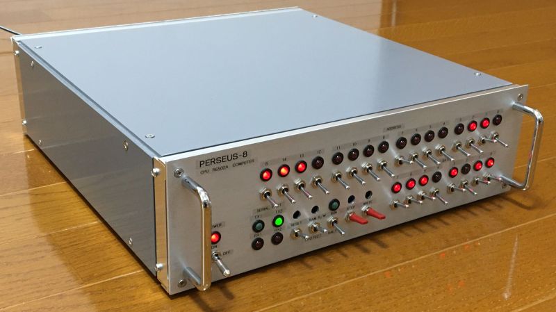
The machine is named PERSEUS-8 by its creator, [Mitsuru Yamada]. It follows earlier machines bearing the PERSEUS badge, all of them completely homebrewed and equally gorgeous. The PERSEUS-8 would have been an impressive machine had it come along 45 years ago — the 2 MHz version of the 6502, a full 16-bit memory address space, and 16 kB of battery-backed RAM. But the mechanical and electrical construction methods and the care and craftsmanship taken are where this build really shines. The case is fabricated out of aluminum sheets and angles and looks like it could have come from a server rack. The front panel is to die for — [Mitsuru] carefully brushed the aluminum before drilling the dozens of holes needed for the toggle switches and LEDs. And the insides are equally lovely — socketed chips neatly arranged on perfboard with everything wired up using period-correct wirewrap methods. Even the labels, both on the front panel and even on the motherboard, are a joy to behold.
Builds like this are the ones that really inspire us to take the extra steps needed to make our projects not only work, but also to be beautiful. We’ve seen this kind of craftsmanship from [Mitsuru] before — recall this serial terminal that never was, or the machine that came before the PERSEUS-8.


I love how he built the chassis – so simple and elegant. I shelved a project thinking I needed a sheet metal brake to bend up the case. I will try this technique for sure. I really like the look of all of his projects’ aluminum enclosures.
Another way to get past this hurdle is to buy a used 2U or 3U rack server. There are tons of them around for not much more than what you would pay for the aluminium stock. You could buy standard 2U or 3U blanking plates for those, into which you can mill and drill your holes and slots.
I am the creator of this computer. I used a sheet metal brake long time ago. However, I prefer the combination of sheet metal and L-angles because I don’t have to make an exact blueprint first, and it is easier to fine-tune the dimensions during the process. I think the strength is inferior to the bending method.
We are honored. This is the most beautiful computer I’ve ever seen, and I’ve seen many Data General and DEC machines.
* no key lock for starting https://img.directindustry.com/images_di/photo-g/38087-2735285.jpg
* it not fit to normal rack (screws stick out of the enclosure)
* no water cooling
* no info about uses memory on front
This the most era correct 1970’s build I have seen. Granted there are IDC connectors and ribbon cable in place of edge connectors and waxed twine wiring looms but if you have ever spent so long with wire-wrap then i think you would understand why.
I think (hope) the guy you responded to was trolling.
look at image http://www.pdp8online.com/pdp8i/pdp8i.shtml key lock in old pdp computer
this is normal in old ’70 computers.
first super computer will be watercoling this is not joke
etc
Pretty. But, there’s a point where form compromises function. I ran machines back in the Dark Ages where bootloaders had to be entered with lights and switches. Toggles were spaced far enough apart so you could get your fingers in there. More obvious groupings so you could read and write nibbles easily. With octal, you could enter a whole nibble with one motion. Not so easy with hex. Store, step and some other buttons were push momentary switches, not spring-loaded toggles. More efficient. And, needs an RS232 console port. Key in boot with switches. Load relocatable loader from paper tape, Load monitor from paper tape and load exe or OS from whatever media was supported.
Doesn’t matter how nice you make something, Hackaday readers will always find a way to shit on it.
Its a nice build and the metal case protects it handsomely. I would enjoy it more with a schematic of the circuit board and photos. A lesson in adding LEDs to your CPU would be helpful.
I’m wondering what the purpose of the switches are.
The full schematic (PDF) and photos are attached in the project page. The many toggle switches are for addressing the memory and writing data to it. For example, you can program using only these toggle switches, just like programming from a PC keyboard. This is shown in the video in the project, so please check it out.
Aw Man, what a beautiful build!
Absolutely love the tradidional point to point wiring as well! There is nothing more relaxing than doing point to point!
Can’t wait to see more!
Why ?
Why so many toggle switches when rotary switches with 8 12 and 16 positions existed in the 60s ?
Front panel afficionados really look like masochists :-O
Properly laid out panel you can hit an entire word one handed in a chord like fashion
In order to minimize the number of standard logic ICs for the Direct Memory Access (DMA) bus control, this computer uses a method that assigns binaries directly to toggle switches and LEDs instead of a rotary switch system. This computer is designed to look like a 1970s minicomputer or early microcomputer.
Yeah, there’s a 6502 design in the Novemeber 1977 Byte that has lots of rotaries and even a hex display. It’s neat, but lots and lots of glue logic.
The rotary switches control f unctions. Toggle switches are used to enter the address and data.
People remember that 6502 article (I think because of the front panel, the KIM-1 was out by then), but nobody mentions tgen article on page 80 abiut building a computer from logic ICs.
Yeah, that was the OISC one, right? I’m surprised I haven’t seen a modern take on that one.
I think people also remember the 6502 one because it pulled out and let you modify the registers and flags, which was unusual for a micro.
HaD is full of people that do things either by lazy pay-to-win or the hard way for better or worse.
One could make 4-bit encoding with old fashion 4 pole 16 throw switch. Funny enough they showed up (out of stock) on walmart site for volume control!? You just need to wire up each pole corresponding to the bit pattern at each positions. Is’t that learning decimal to binary?
I have some rotary switches SCSI 2 drive ID for hex.
FYI:
Omron Electronics A7BS-254-1 Thumbwheel Switch Hexadecimal 0.1A @ 50VAC/28VDC Panel Mount, Snap-In
Digikey stocks them and they are cheaper and more attractive than the old fashion stuff.
https://www.digikey.com/en/products/detail/omron-electronics-inc-emc-div/A7BS-254-1/368277
Cognitive load, for one thing.
Your eyes have to get involved, to work rotary switches. Where is it now, where is it going, click click click are we there yet click click, ok! And that’s two 16-position ones for a single 8 bit byte.
As compared to a row of 8 toggle switches – you can actually feel the bits. No need to even look. Important when you’re trying to keep your place on a page full of hex numbers. A9? Up down up down up down down up.
100% agree. I did two different systems with switch panels. The first used all toggle switches, the second, octal thumbwheels for addresses and toggles for data (that was a Z-80 system, so octal was my radix of choice). Even when storing programs in sequential locations, the toggle switches were just as fast as the thumbwheels. The only real advantage was that the thumbwheels took up less panel space, so the whole front panel fit into a box made for storing ten 3.5″ floppies.
When using the thumbwheel panel, the big risk was overwriting your code by forgetting to carry to the next digit, which didn’t happen with toggle switches because there was muscle memory that handled that – when incrementing, the carry was very nearly automatic. With the thumbwheels, there was no perceptual difference between going from 6 to 7 and going from 7 to 0.
Good times.
This sort of thing is nostalgia for an illusion.
The Altair 8800 (and 680) and Imsai had panels full of switches, but it dropped off pretty fast. You needed them at that precise time. Nobody knew what they were going to do with their own computer, you needed a way to get data in and out of the CPU, and besides, microcomputers had them. It made sense when a computer came with 256 bytes of RAM, you couldn’t do much anyway, but with no front panel, you couldn’t do anything at all. (We see the same thing later, comouters aimed at a broader market includes BASIC so you could do something out of tge box.)
But these front panels not only needed all those switches, but lots of gates to interface it with the bus. It added complexity and cost, yet soon after yiu’d basically throw it all away.
But very rapidly there were video boards or external terminal. And monitors in ROM. So soon you didn’t even need the switches to enter a loader to bring in real programs.
Yes, there were actual construction articles that had panels like this, an astronaut described one in Kilobaud, and there was that one in Byte for the 6502 (which is the onky instant I remember for the 6502), but they were less common than imagined.
And like I said previously, calculator style keypads and readouts that did become common (on most 6502 systems, but also I have an Intel single board computer) had a monitor in ROM. So the computer was constantly running a program, so the “front panel” never needed extensive hardware to load the RAM directly.
Nobody would use front panel switches any longer than they had to.
Disclaimer: I haven’t looked at the schematic.
>But these front panels not only needed all those switches, but lots of gates to interface it with the bus.
The address/data can be injected into the uP bus while it is tristated with a 4.7K series resistor connected to the switch so it is either pull up/down.
While the 6502 doesn’t have an external bus enable pin like the 6501, it does tristates the bus during the first half of each cycle, then accesses memory during the second. If you want to do it properly, it takes like 3 octo buffers to buffer and tristate the bus.
I’m talking historically. The Altair 8800 front panel was complicated. It’s not just getting data into RAM, you have to address it (and if you want things easy, a string of presetable counters so you can load a base address, but advance by pressing a “load” switch). In retrospect there were ways of simplifying it, but that didn’t happen until after the brief time front panels existed.
When this came up before, someone mentioned the 1802, the COSMAC Elf was maybe the one specific computer built by many. But the 1802 was designed that way, so the program counter could be used to address ram while loading ram from switches, and then a button press would advance the program counter.
There were later schemes for jamming “NOP” into the databus so the CPU couod do much of the work, but that came later.
A monitor in ROM was so much easier.
Love this, especially the hand drawn schematics. They have a Forrest Mims vibe that really fits the period. The serial terminal is lovely, too! Nice work!
Thanks, I just looked up Mr. Forrest Mims. My homemade serial terminal is useful for testing because it works as soon as I turn it on.
Obligatory HAD link: https://hackaday.com/2017/01/18/forrest-mims-radio-shack-and-the-notebooks-that-launched-a-thousand-careers/ Mims is the best. I still have some of these guides and I learned a lot from them. The aesthetic pushes all the nostalgia buttons for me.
I took a deeper look at your terminal page and I’m adding that to my list of projects to replicate. I’ve messed with 68xx machine code on an ET-3400 and have some other serial-driven, retro projects in various states of chaos that this would compliment nicely! Thanks again for sharing!
I recall seeing a similar build in an old BYTE magazine from, 1976 ?
This is way nicer than real homebrew computers of the period. And I mean that in a positive way. We would have wished for something this well put together.
I can’t wait to see what peripherals you use.
Right? This thing is beautiful. Imagine pairing it with an 8 inch floppy drive. Shiny!
Thanks. This computer is 70’s style, but it has full RAM space battery backup, which was probably not available back then. This makes it easy to use because you don’t have to re-install the programs every time the power is turned on. I believe you can enjoy machine language by toggle switches, and simple interpreters on such a computer.
Wow!
(Now I am musing about putting one of my old Intel SDK boards into an enclosure)
I like the retro, both in the case design and the functional switch panel.
I would pass on the wire-wrap construction though. Time spent on PCB layout would be far more valuable, appropriate for this era of computer, and cost less even for a one-off.
My first computer was an 8008 and I had to input the program by hand I was my own compiler all machine code. I learned a lot.
2nd computer a s100 buss z80, and had to put in the boot loader by hand. All days I am glad are gone.
But never did I have something this beautiful that was done here.