Those of us who have bought cheap TinyVNA devices for our RF experimentation will be used to the calibration procedure involving short-circuit, 50 Ω, and open terminations, followed by a direct connection between ports. We do this with a kit of parts supplied with the device, and it makes it ready for our measurements. What we may not fully appreciate at the level of owning such a basic instrument though, is that the calibration process for much higher-quality instruments requires parts made to a much higher specification than the cheap ones from our TinyVNA. Building a set of these high-quality parts is a path that [James Wilson] has taken, and in doing so he presents a fascinating discussion of VNA calibration and the construction of standard RF transmission line components.
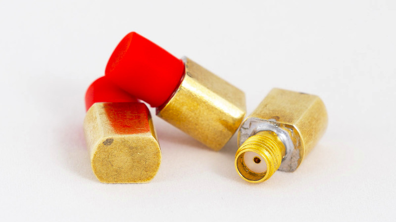
We particularly like the way that after constructing his short, load and open circuit terminations using high-quality SMA sockets, he put a custom brass fitting 3D printed by Shapeways on the end of each to make them easier to handle while preserving their RF integrity. If we’d bought a set of terminations looking like these ones as commercial products we would be happy with their quality, but the real test lay in their performance. Thanks to a friend he was able to get them tested on instruments with much heftier price tags, and found them to be not far short of the simulation and certainly acceptable within his 3 GHz range.
Curious about VNAs at the affordable end of the spectrum? We took a look at the TinyVNA, which while it is something of a toy is still good enough for lower frequency measurements.


I don’t really see the benefit of DIY your own calibrators, when the BOM seems to be going over 50$, considering what the NanoVNA costs from china. The most interesting part is definately the 50 Ohm load resistor, but to me it looks like simulation and measurements are not really agreeing there anyway, so a cheap bought standard would have probably performed just as good.
Would have been interesting to compare his DIY efforts with the calibration standards that come with the high end VNAs that were used to make the measurements.
https://hackaday.com/2021/05/08/reinventing-the-wheel/
> Would have been interesting to compare his DIY efforts with the calibration standards that come with the high end VNAs that were used to make the measurements.
That is *exactly* what those measurements already are. The high-end VNA has to be calibrated against those standards before measuring the DIY ones has any meaning. There is no other ground truth in the VNA to compare against, otherwise there would be no need for the calibration in the first place.
I buy cal kits frequently for my job, most are in the $10K+ price range. I can’t imagine that a $50 BOM gives results that are worthwhile.
Do people actually use these things. Mine cost £35 k when I bought it new in the mid 90s and has been sitting in a pelican case in the back yard for at least 20 years along with its HP calibration set and the rest of its S parameter set, EMC antennas and cables.
Sure they do!
I use VNA’s at the very least weekly along with my spectrum analyzer. I use them more than my oscilloscope!
And as said the professional calibration standards cost a lot, so diying them is not out of the question.
I have done that many times as surplus VNA’s rarely come with calibration kits.
And a simple SOL kit is a good companion for antenna analyzers as well.
Uhh… yeah? I use one every couple months, a coworker uses them weekly and another uses a third daily. You making a bad purchase doesn’t mean the tool is useless. Anybody doing RF, transmission lines or inductive coupling uses them constantly.
Not a bad purchase. It was used when I got it for my thesis and rarely since but it owes me nothing even though it cost so much. I wish I could find some education facility that wanted it but no one does. I have offered it to a couple of maker spaces and the local university but they are not interested though given the lack of education that seems to take place at universities these days I am not really surprised.
If you are interested in designing and building HF radio gear the nanoVNA is simply awesome. Relative to 20 years ago the advance is huge. For around $500 US you can have a 100 MHz DSO, nanoVNA, tinySA, several 4.5 digit DMMs, a 60 MHz AWG and an LCR/transistor tester. That’s a fantastic set of kit for designing and testing HF QRP gear. It’s not as good as old HP kit, but it takes a *lot* less space and is quite a lot more affordable.
I really like the approach and effort James has taken to get to better characterised MSO calibration standards in the first place, he’s certainly up the right path, however there are a few things that must be considered:
First there is the issue that VNA calibration standards generally present a kind of chicken and egg problem – when you design new standards, you need other well known and characterized standards and a complete model of the transmission line effects to generate the generally used third order polynomal fitting model of L/C coefficient used for coaxial MSO standards. In the end you at first just build upon the fact, that somebody else characterized a different cal-kit and you inherit all of its errors, including your modelling errors and uncertainty introduced by the repeatability of the connectors and your handling of the standards.
Second there is the issue, that the reflectometer error model (i.e. S11) in a VNA isn’t able to accout for any imperfections in the calibration standards – it’s unfortunately just garbage in, garbage out. You’ll get nice smooth magnitude and phase response from malformed calibration kit parameters (offset lengths and polynomal coefficients), but the error compared to the reference plane and the device under test can be huge – but completely hidden to the operator by the nature of the mathematical model. This is also true for re-measuring the calibration standards after a calibration was performed – they are not linear independant.
The only way arround this issue is to perform so called verification measurements, which use precision 50 Ohm and 25 Ohm air dielectric coaxial lines in combination with a known good match andort to perform a residual source match and ripple test verification measurements. It is important, that these components are independent from the ones used for calibration due to the math involved. An interesting document lining out the procedures to verify your calibration and estimate the errors, including the ones introduced by the calibration standards, are the EURAMET Guidelines on the Evaluation of Vector Network Analysers (VNA).
https://www.euramet.org/Media/news/I-CAL-GUI-012_Calibration_Guide_No._12.web.pdf
The same issue is also present in the classical SOLT uni- and bi-directional error models often used for two port calibation.
Air dielectric coaxial verification lines however defeat the purpose of developing homebrew calibration standard in the first place, as if you can afford them, you could have easily purchased 5 calibration kits with certificates instead ;) The 50 Ohm ripple test can however be performed using a known good semi-rigid line, preferably with an independant measurement performed by the manufacturer, as the verification measurements are performed against the assumed ideal 50 Ohms of transmission line impedance of the line.
Unfortunately the match or load standard is also often defined as just having an S11=0 in the math of most older VNAs, as it vastly simplifies the math – if you can’t build it to spec (i.e. S11 < 30..40 dB over f of interest), your pretty much screwed and your residual directivity error coefficients in the error model will be all over the place – and you won't even notice (see above).
If you need something repeatable using off the shelf components for frequencies up to 4 GHz that doesn't kill the bank (i.e. < 100$), I can recommend fetching a Rosenberger SMA 50 Ohm load, a short and an (f)-(f) adapter from the usual suspects (Mouser, Digi-Key) and use the coefficients, offset lengths, and part numbers shown here
https://hhft.de/sma-cal-kit
Great comments! The web page doesn’t seem to show part numbers for the short or through parts. Does that mean they’re all the same, or is there something specific to look for? Thanks!
Just saw this posted a thanks for the info! I’m curious to see how well I can do a ripple test with the equipment I have.
Many VNAs (including mine) now have the ability to accept full S1P characterizations of the calibration standards. The script I wrote will print out the calculated delay/length and polynomial coefficients, but using the S1P outputs means the VNA can make better assumptions than S11=0 everywhere for the load standard.
Useful info! I want to echo John’s concern on the missing part no. for the short (f). I have searched high & low for it on Mouser, Digikey, Telegartner & H+S, but nothing resembled the website’s drawing. Fairview SC2140 came the closest, but it is 8.13 mm long vs. the drawing’s 9.8 mm. Additionally, the offset length of 1.96mm given by the article is suspiciously short because the SMA’s reference plane is specified at the articulating face of the dielectric
At first glance the cover picture looked like small tubes of on-the-go lipstick.
You can make a better open circuit standard by removing the pin and dielectric from the SMA connector, leaving just the housing. The resulting empty housing acts like a circular waveguide, which has a really high cutoff frequency (like 20-40 GHz), so it acts as a true open. An unmodified SMA connector however has a tiny pin at the end, which acts as an antenna, albeit a terrible one. But it still has an effect on higher frequencies.
What I’m missing in this article and the creation of the calibration set is that you need to calibrate your VNA every time you start a new measurement. Sometimes it is even preferable to calibrate the VNA again and repeat the measurement.
For the best results we want to have the calibration in close resemblance of the target we are measuring: Use the same cables and same SMA. Preferably don’t move or touch the cables between setups. The reason is that every connector and every cable is different and the calibration will nullify the differences and isolate the measurement.
The calibration process is a bit tedious but you’ll get through it quickly enough once you get the hang of it. The best one I’ve used was from Magiq. While not in the hobby realm it’s very good for what it can do.